Cloud communication center system and method for processing data in a cloud communication system

a communication center and cloud technology, applied in the field of cloud communication center network technology, can solve the problems of delay in communication between the radio units and large amount of resources and high processing power in the digital unit center, and the network of the communication center may require expensive operating expenses (opex)

Active Publication Date: 2012-06-28
KT CORP
View PDF4 Cites 18 Cited by
  • Summary
  • Abstract
  • Description
  • Claims
  • Application Information

AI Technical Summary

Benefits of technology

[0023]The at least one base station may include a remote unit and a physical-layer function unit. The remote unit may be configured to transmit and receive the radio signals to / from the user equipment. The physical-layer function unit may be configured to process the radio signal according to a physical layer of a radio interface protocol. The central office may include a centralized unit that may be configured to process the radio signal from the base station according to at least one of a media access control layer, a radio link control layer, a packet data convergence protocol layer, and a radio resource control layer.
[0024]The at least one base station and the central office may be coupled together through an inter-protocol interface supporting a data transmission rate of about hundreds of megabits per second (Mbps). In this case, the inter-protocol interface may be a transport channel that couples the physical layer and the media access control layer.
[0025]The central office may include a control unit that may be configured to control signal transmission and signal reception of the at least one base station and the central office.

Problems solved by technology

Due to such requirements, the cloud communication center network may require expensive operating expenditure (OPEX) to maintain such an optical interface.
Accordingly, the digital unit center requires a large amount of resources and high processing power as compared to the radio unit at the base station.
Such a processing load may cause a delay in communication between the radio units and the digital unit center.

Method used


Image

  • Cloud communication center system and method for processing data in a cloud communication system
  • Cloud communication center system and method for processing data in a cloud communication system
  • Cloud communication center system and method for processing data in a cloud communication system

Examples


Embodiment Construction

[0034]Reference will now be made in detail to embodiments of the present invention, examples of which are illustrated in the accompanying drawings, wherein like reference numerals refer to like elements throughout. The embodiments are described below, in order to explain the present invention by referring to the figures.

[0035]Unless explicitly described to the contrary, the word “comprise” and variations such as “comprises” or “comprising,” will be understood to imply the inclusion of stated elements but not the exclusion of any other elements.

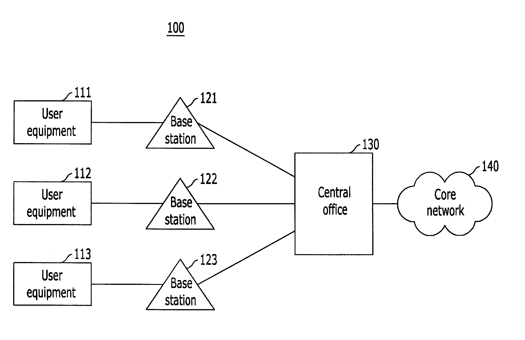
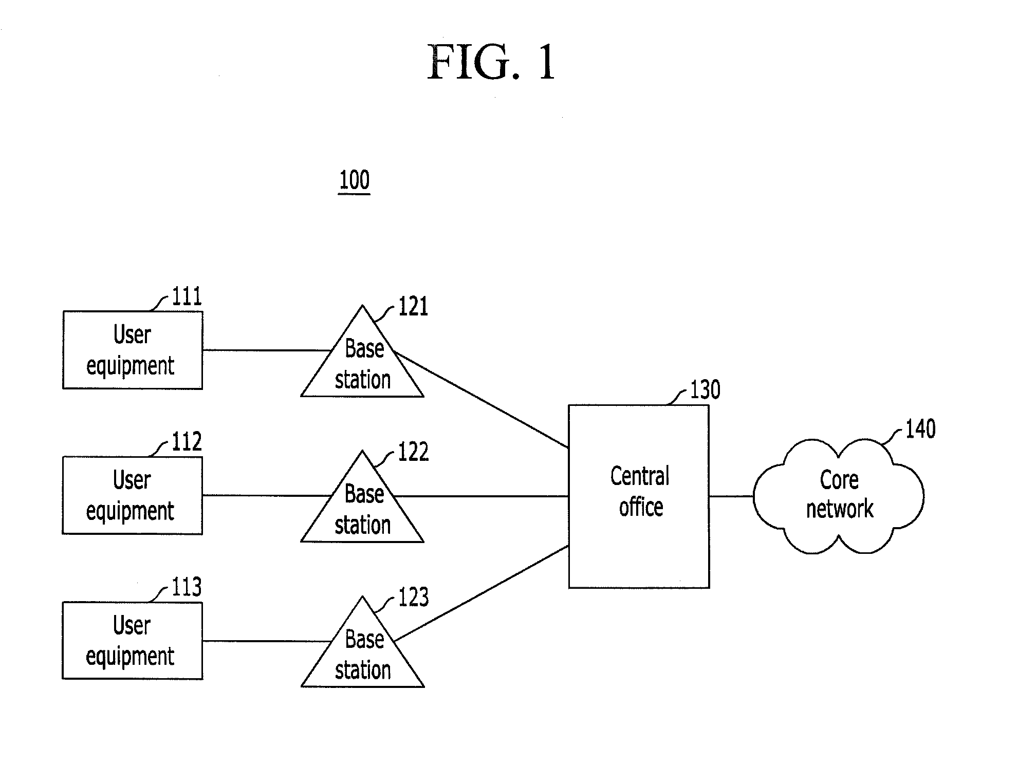
[0036]The term “user equipment” as used herein may refer to any of a terminal, a mobile station (MS), a mobile terminal (MT), a subscriber station (SS), a portable subscriber station (PSS), and an access terminal (AT), and may include some or all of the functions thereof.

[0037]The term “base station (BS)” as used herein may refer to any of an access point (AP), a radio access station (RAS), a node B, an evolved node B (eNodeB), a base transcei...


PUM


Abstract

Cloud communication center system and method for processing data in a cloud communication system. An apparatus for supporting a cloud communication system may include at least one remote unit and a centralized unit. The at least one remote unit may be configured to process one of radio signals received from a user equipment or radio signals to be transmitted to a user equipment according to at least one sub-layer of an open system interconnection reference model. The centralized unit may be configured to receive the processed signal from the remote unit and to process the received signal based on the remaining sub-layers of the open system interconnection reference model.

Description

CROSS REFERENCE TO PRIOR APPLICATIONS[0001]The present application claims priority under 35 U.S.C. §119 to Korean Patent Application No. 10-2010-0132487 (filed on Dec. 22, 2010), which is hereby incorporated by reference in its entirety.FIELD OF THE INVENTION[0002]Apparatuses and methods consistent with the present invention relate to a cloud communication center network technology, and more particularly, to a cloud communication center system and a method for processing data in a cloud communication center system.BACKGROUND OF THE INVENTION[0003]A cloud communication center network technology has been introduced to more efficiently utilize network resources. The cloud communication center network technology may greatly reduce operational expenditure and power consumption while increasing radio data capacity. Due to such advantages, the cloud communication center network technology has attracted much attention.[0004]Typically, a radio unit and a digital unit are implemented as a sin...

Claims


Application Information

Patent Timeline
Patent Type & Authority Applications(United States)
IPC IPC(8): H04B7/00H04W4/00H04W4/60
CPCH04W4/003H04W88/085H04W4/00H04W92/10H04W80/02H04W80/04H04W80/06H04W72/0413H04W4/60H04W16/18H04W72/21
Inventor LEE, KI-HOPARK, JONG-HO
Owner KT CORP
Why Eureka
Try Eureka