
Surgical guiding tool, methods for manufacture and uses thereof

a technology of surgical instruments and guiding points, which is applied in the field of surgical guiding tools, can solve the problems of inconvenient use, inability to fix the implant to the bone, and unstable devices, and achieve the effect of saving time during placement and stable and accurate guidance of surgical instruments

Inactive Publication Date: 2012-06-28
MATERIALISE NV
View PDF16 Cites 69 Cited by
  • Summary
  • Abstract
  • Description
  • Claims
  • Application Information

AI Technical Summary

Benefits of technology

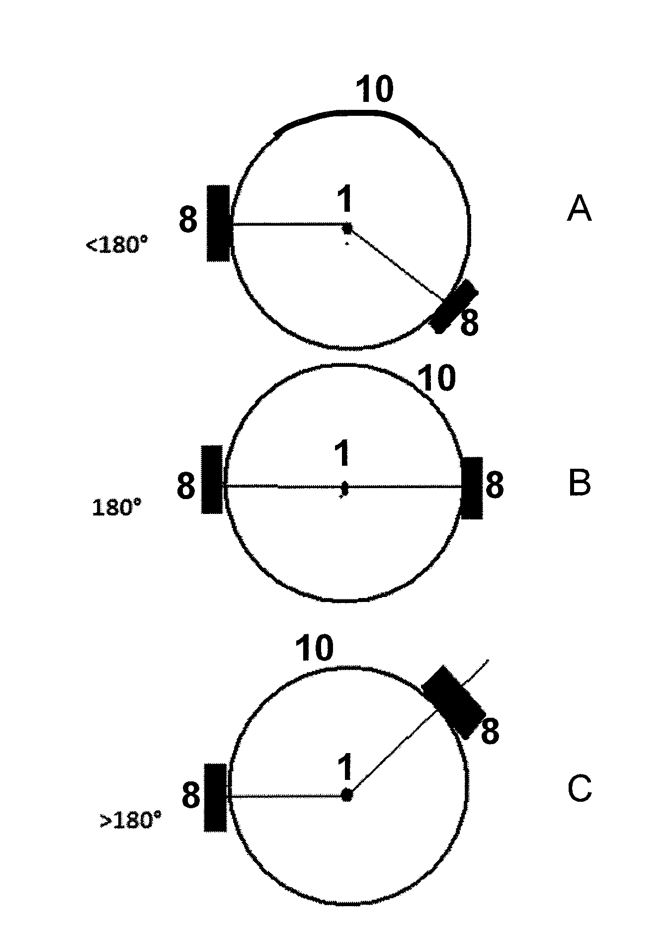
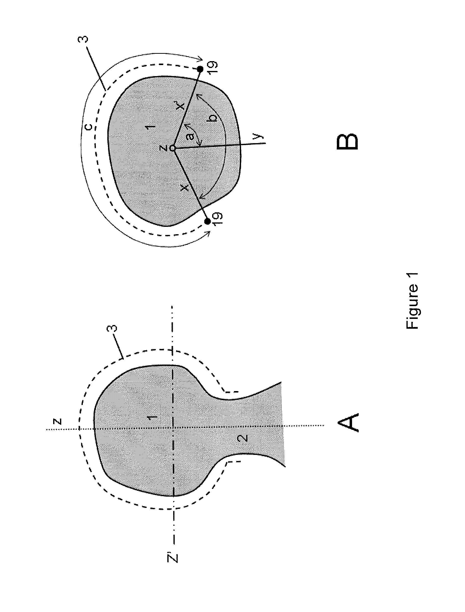
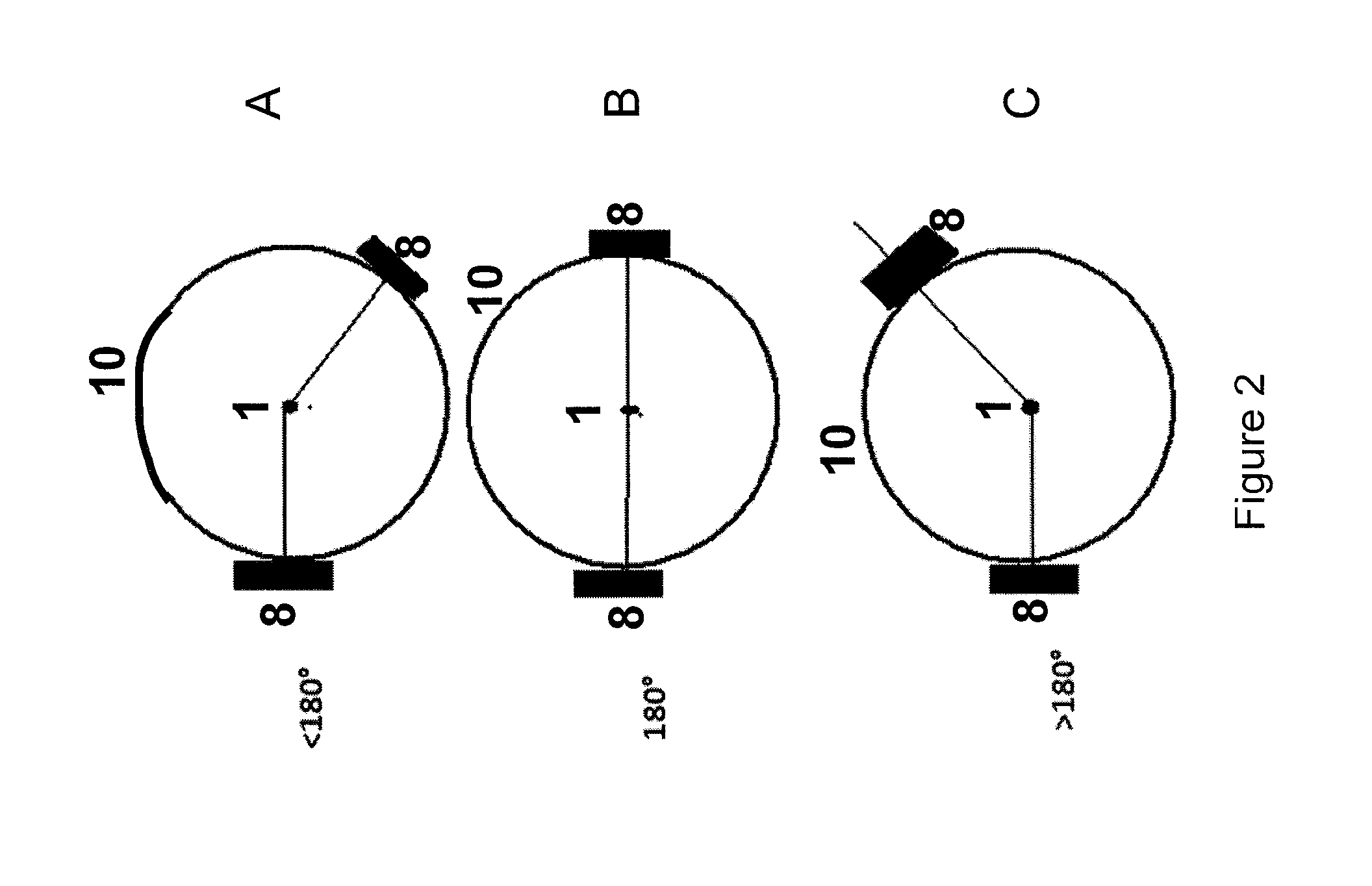
[0011]The present invention relates to patient-specific surgical guiding tools for a bone head which can be generated based on a CT scan (i.e. without requiring segmentation of the cartilage) and nevertheless provide stable and accurate guidance of the surgical instrument. Moreover, as the tool ensures a direct fit in the desired position, no alignment is necessary upon, which saves time during placement.
[0019]In particular embodiments, the devices of the present invention comprise at least one component which is made by additive manufacturing. This allows the integration of a patient-specific component which further increases the accuracy of the guiding tools. Indeed, the guiding tools of the prior art are typically standard tools which can at most be adjusted mechanically to fit every patient, but do not ensure the patient-specific fit and accuracy.

Problems solved by technology

Moreover, there is more chance that the natural gait is recovered and the stress is transferred in a natural way through the neck of the femur rather than immediately on the thigh (which often causes pain).
Improper placement or positioning of the implant will not only result in a failure to restore the clinical bio-mechanics of the joint but will result in inadequate fixation of the implant to the bone.
These devices are often unstable as they do not fit perfectly on the patient's bone and in some cases inaccurate because of the great distance between the supporting anatomy and the planned point of entry of the surgical instrument.
Indeed, as a large part of the head of a limb bone is covered with cartilage, this surface is smooth and slippery which makes it less suitable as secure attachment point.
Cartilage is very difficult to segment on CT-images and even using MRI implies an additional step which is time-consuming.
Thus it is very difficult to design structures precisely fitting on to the bone head.
In addition, the prior art devices such as those referred to above are all quite bulky, mainly due to the presence of extended support arms and thus require the availability of a large surgical window.

Method used


Image

  • Surgical guiding tool, methods for manufacture and uses thereof
  • Surgical guiding tool, methods for manufacture and uses thereof
  • Surgical guiding tool, methods for manufacture and uses thereof

Examples


Embodiment Construction

[0053]The present invention will be described with respect to particular embodiments but the invention is not limited thereto but only by the claims. Any reference signs in the claims shall not be construed as limiting the scope.

[0054]Where the term “comprising” is used in the present description and claims, it does not exclude other elements or steps. Where an indefinite or definite article is used when referring to a singular noun e.g. “a” or “an”, “the”, this includes a plural of that noun unless something else is specifically stated.

[0055]Furthermore, the terms first, second, third and the like in the description and in the claims, are used for distinguishing between similar elements and not necessarily for describing a sequential or chronological order, unless specified. It is to be understood that the terms so used are interchangeable under appropriate circumstances and that the embodiments of the invention described herein are capable of operation in other sequences than desc...


PUM

PropertyMeasurementUnit
angleaaaaaaaaaa
angleaaaaaaaaaa
angleaaaaaaaaaa

Abstract

The present invention provides surgical guiding tools for surgery on a bone head comprising a cutting component, a guiding component and a collar comprising a patient-specific component, which are interconnected and which ensure secure and accurate placement of the guiding tool and thus guarantee accurate implementation of the pre-operative planning of the surgical intervention.

Description

FIELD OF THE INVENTION[0001]The present invention relates to surgical guiding tools which are of use during limb bone surgery, more specifically during limb bone resurfacing surgery for guiding a surgical instrument. The present invention further relates to methods for manufacturing these tools and specific methods for using the surgical guiding tools of the invention in limb bone resurfacing surgery.BACKGROUND[0002]One of the options in the treatment of advance joint arthrosis is joint resurfacing, i.e. removing only the diseased or damaged surfaces of the head of the bone. In the United States, hip resurfacing was first approved by the FDA based on the Birmingham Hip Resurfacing (BHR) technology developed by Derek McMinn. The BHR has a mushroom shape with a metal cap for placement on the femur head which fits into a cup placed in the acetabulum. The cap is fixed onto the head of the femur by way of a very small stem which is introduced through the femur head (and neck)[0003]Hip re...

Claims


Application Information

Patent Timeline
Patent Type & Authority Applications(United States)
IPC IPC(8): A61B17/56B23P11/00
CPCA61B17/175Y10T29/49826A61B2019/505A61B2034/105B33Y80/00
Inventor DE SMEDT, KARLAGELAUDE, FREDERIKCLIJMANS, TIM
Owner MATERIALISE NV
Learn More