
Golf ball manufacturing apparatus

a manufacturing apparatus and golf ball technology, applied in the field of golf ball manufacturing apparatus, can solve the problems of poor quality of injection molding machine screw, large time and labor requirement for storage control, and inability to accurately measure the mixture, etc., and achieve the effect of ensuring uniformity of quality, reducing labor intensity and cost, and ensuring quality

Inactive Publication Date: 2007-05-29
DUNLOP SPORTS CO LTD
View PDF17 Cites 0 Cited by
  • Summary
  • Abstract
  • Description
  • Claims
  • Application Information

AI Technical Summary

Benefits of technology

"The present invention is a golf ball manufacturing apparatus that includes a mold, an injection molding machine, a supply portion, and a crushing machine. The apparatus also includes a main cylinder and a cylinder for regenerating pellet and virgin pellet which branch upward from the main cylinder. The apparatus is designed to prepare a regenerating pellet by crushing a residue discharged from the mold. The apparatus also includes an angle between the cylinders for regenerating pellet and virgin pellet of up to 20 degrees, and a detecting device for detecting a residual amount of virgin pellet. The residue is used at a predetermined rate and does not stay but is used each residue as it is generated, resulting in a stable flow of resin to the process and maintaining uniformity of quality. The apparatus is cost-effective, efficient, and stable."

Problems solved by technology

A great deal of time and labor is required for a storage control, a measurement and the like for the mixture, and a process is also complicated.
By the moisture absorption, a change is generated, that is, when a mixed resin pellet is subjected to injection molding, it is poorly pulled into the screw of an injection molding machine.
Due to such a change in the flow of the resin, a molding failure such as a beard or a weld is generated in a hold pin portion.

Method used


Image

  • Golf ball manufacturing apparatus
  • Golf ball manufacturing apparatus
  • Golf ball manufacturing apparatus

Examples


Embodiment Construction

[0019]The present invention will be described below in detail based on a preferred embodiment with reference to the drawings.

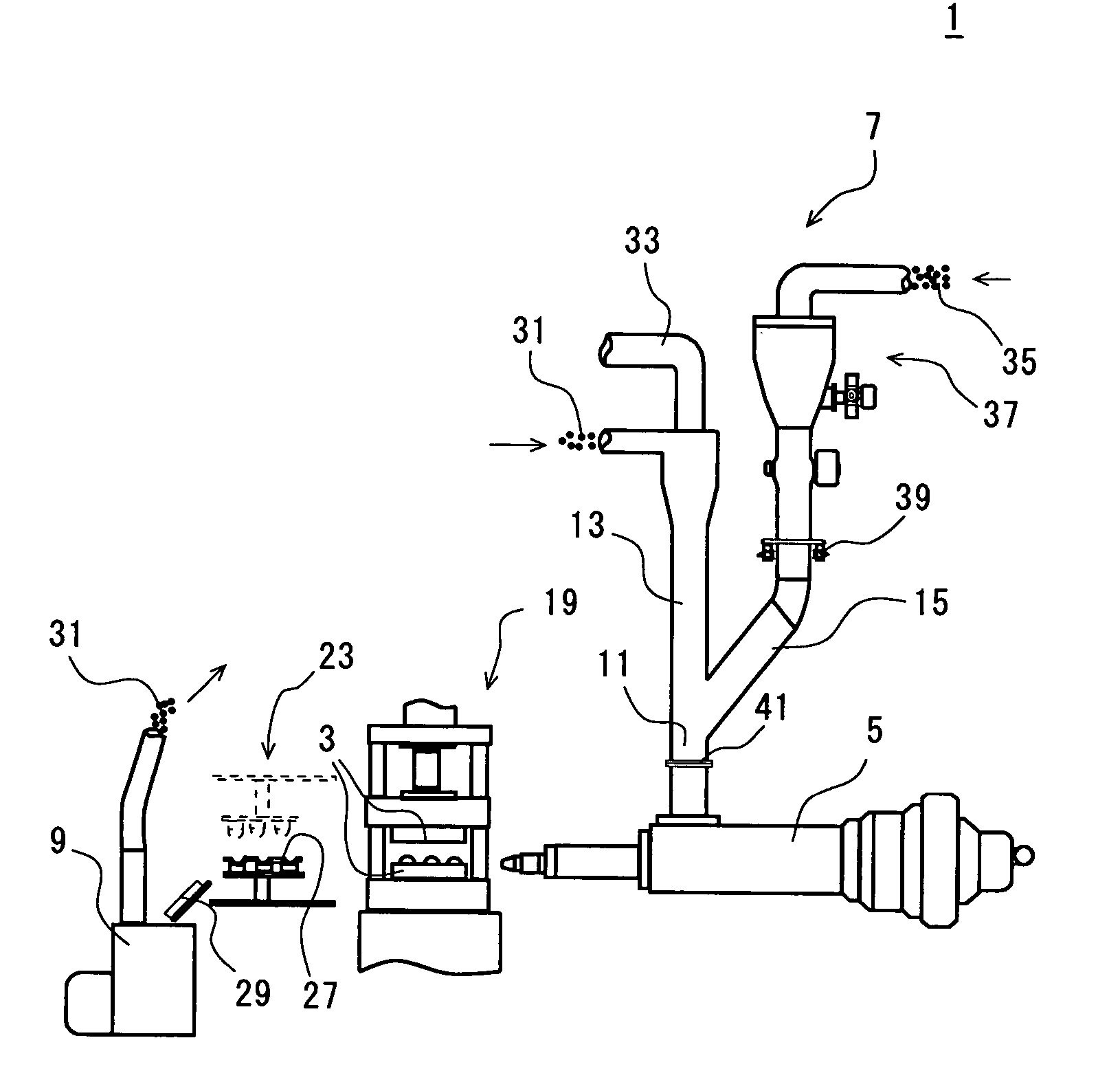
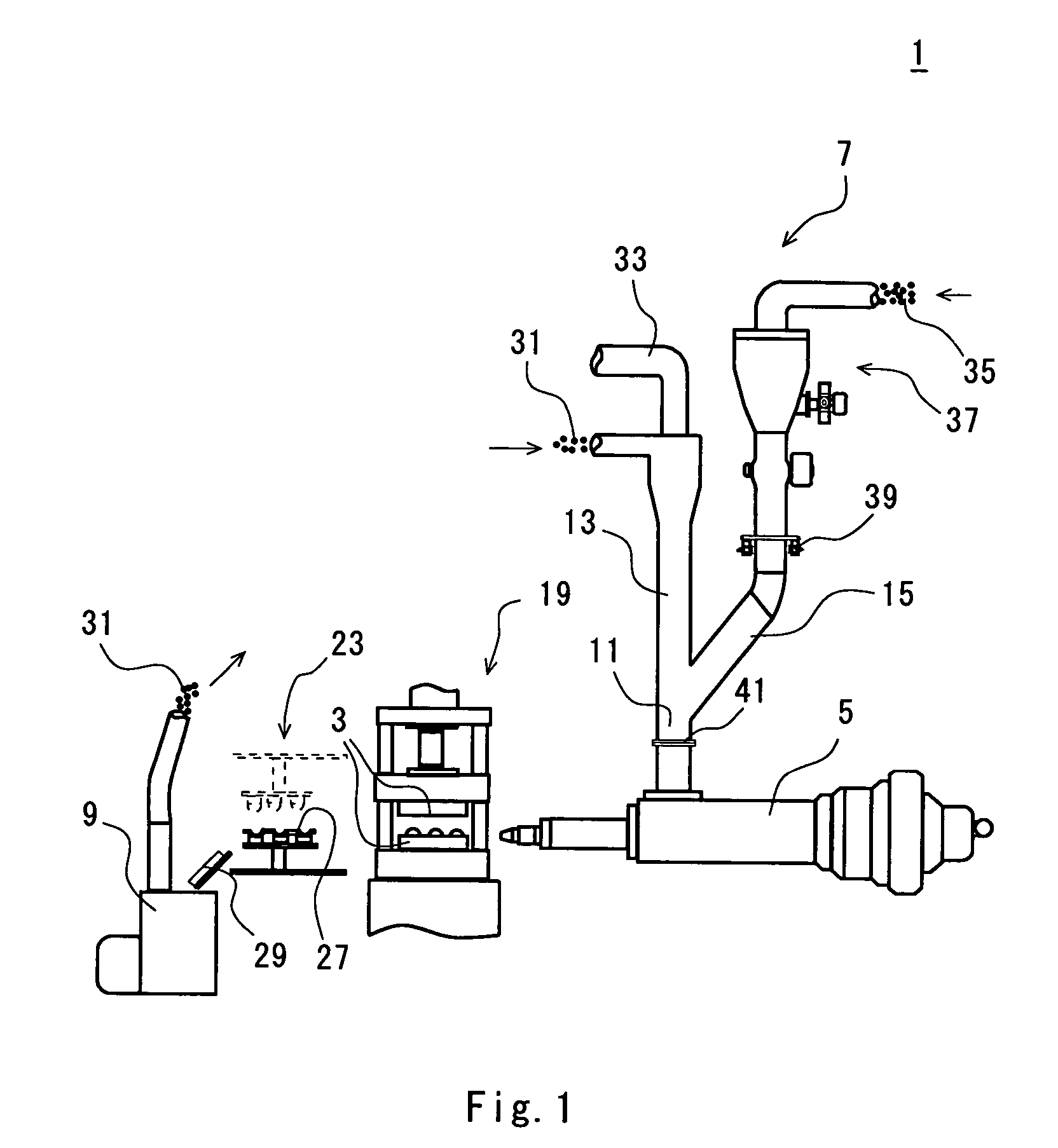
[0020]A manufacturing apparatus 1 shown in FIGS. 1 and 2 comprises a mold 3, an injection molding machine 5, a supply portion 7 and a crushing machine 9. The supply portion 7 includes a main cylinder 11, and a cylinder 13 for a regenerating pellet and a cylinder 15 for a virgin pellet which branch upward from the main cylinder 11. The crushing machine 9 is coupled to the cylinder 13 for a regenerating pellet. The golf ball manufacturing apparatus 1 comprises equipment for handling or controlling a material and a product together with or separately from these units.

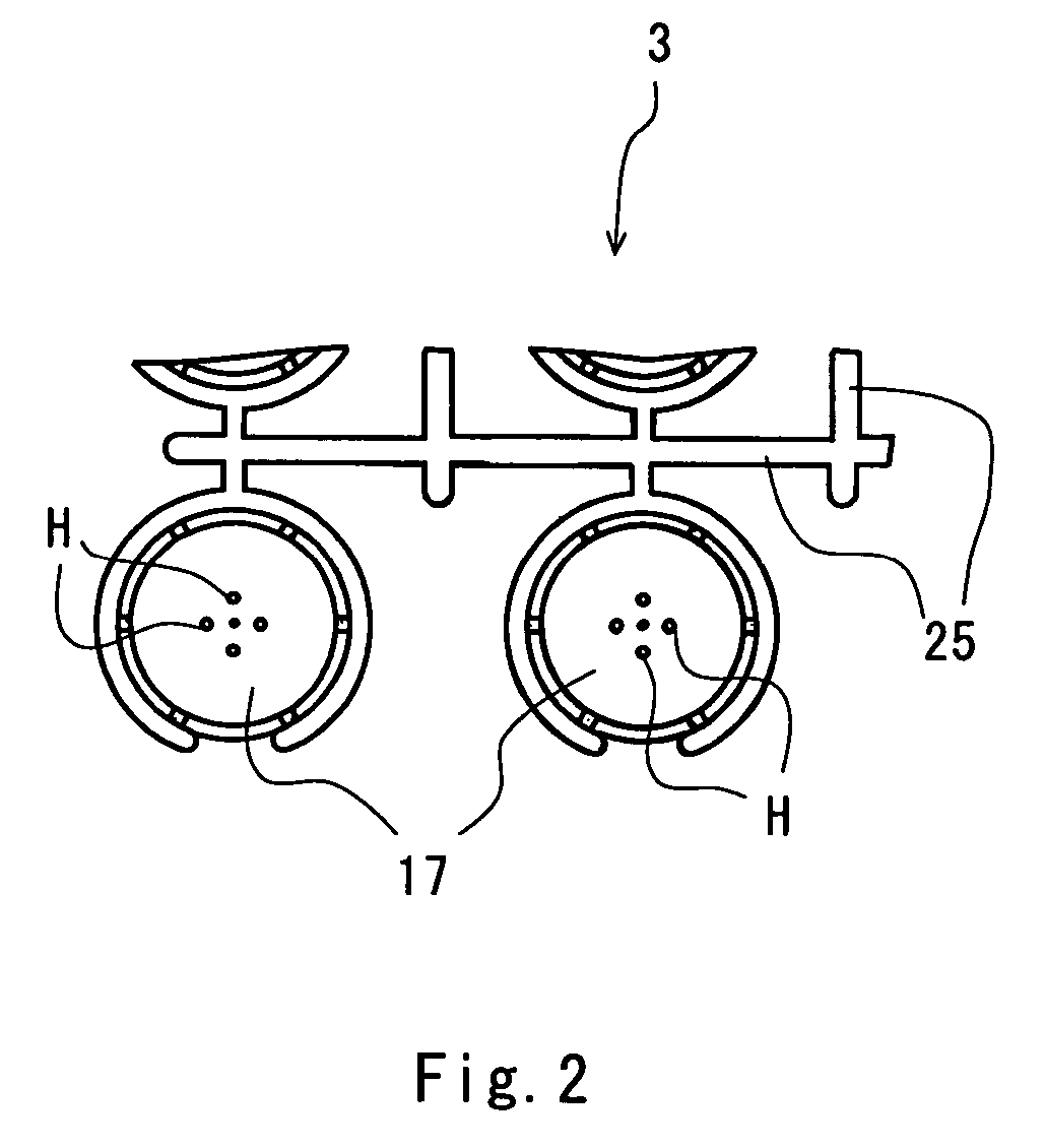
[0021]The mold 3 has an upper mold half and a lower mold half, each of which has a plurality of semispherical cavities 17. Each of the cavities 17 of the mold 3 has a dimple which is not shown. The upper and lower mold halves are united to form a cavity taking the shape of a golf ball. The mold 3 is ...


PUM

PropertyMeasurementUnit
inclination angleaaaaaaaaaa
angleaaaaaaaaaa

Abstract

A golf ball manufacturing apparatus comprises a mold including a cavity for forming a golf ball, an injection molding machine for supplying a molten resin to the mold, a supply portion for supplying a resin pellet to the injection molding machine, and a crushing machine for crushing a residue discharged from the mold, thereby fabricating a regenerating pellet. The supply portion includes a main cylinder (11), a cylinder (13) for a regenerating pellet and a cylinder (15) for a virgin pellet which branch upward. An inclination angle (u) to a vertical line of the cylinder (13) is equal to or smaller than 20 degrees. An inclination angle (f3) to a vertical line of the cylinder (15) is 30 to 60 degrees. The crushing machine is coupled to the cylinder (13), and the regenerating pellet is transferred to the main cylinder (11) through the cylinder (13).

Description

[0001]This Non-provisional application claims priority under 35 U.S.C. § 119(a) on Patent Application No(s). 2003-351459 filed in Japan on Oct. 10, 2003, the entire contents of which are hereby incorporated by reference.BACKGRANULATE OF THE INVENTION[0002]1. Field of the Invention[0003]The present invention relates to a golf ball manufacturing apparatus.[0004]2. Description of the Related Art[0005]A golf ball is usually formed by covering a mid layer of a thermoplastic resin or an outer layer such as a cover of a thermoplastic resin with a core by means of a mold. At this forming step, an excess material (a residue) such as a spew composed of a remaining material is generated when the outer layer is formed. The residue is granulated like a pellet by means of a crushing machine after it is collected to reach a certain amount. A place for storing the residue is required for the collection. The pellet thus granulated is reused together with an unused virgin resin pellet.[0006]The resid...

Claims


Application Information

Patent Timeline
Patent Type & Authority Patents(United States)
IPC IPC(8): B29C45/14B29C45/18B29C31/02B29C45/17B29C31/10B29D99/00B29L31/54
CPCB29C31/02B29C31/10B29C45/1816B29D99/0042B29K2105/26B29L2031/54B29L2031/545
Inventor KOMATSU, SATORUKAJIWARA, TERUO
Owner DUNLOP SPORTS CO LTD
Learn More