
Method And System For Depalletizing Tires Using a Robot

a robot and tire technology, applied in the field of robot-directed depalletizing tires, can solve the problems of not being able to automate unloading of tires, not being able to depalletize tires in a stacking pattern that is unknown in advance, and not being able to organize or only partially organize tires. the effect of palletizing

Inactive Publication Date: 2010-10-28
KUKA ROBOTER
View PDF15 Cites 35 Cited by
  • Summary
  • Abstract
  • Description
  • Claims
  • Application Information

AI Technical Summary

Benefits of technology

The invention is a method and system for depalletizing tires using a robot and a gripping tool. The method involves detecting the position and orientation of the tires and the carrier, and calculating movement paths for the robot to grip and unload the tires without colliding with the environment. The system includes a multi-axis robot, a 3D sensor, a movement mechanism for the sensor, and an evaluation unit or computer to analyze the sensor data and the geometry of the tires and carrier. The method and system allow for the automation of unloading tires from carriers, reducing the physical hard and monotonous work of unloading and ensuring uniform quality and output.

Problems solved by technology

However, even given a precise knowledge of the depositing position during the palletizing, an automatic unloading of the tires has still not always previously been possible since the stacking patterns for the most part vary somewhat during transport and the original, known tire positions and orientations then no longer coincide with the actual position of the tires.
However, these solutions do not use a robot but rather use multi-axle portal systems that are employed both for palletizing and for depalletizing tires.
A depalletizing of unorganized or only partially organized tires or of tires in a stacking pattern that is unknown in advance is not possible with this method.

Method used


Image

  • Method And System For Depalletizing Tires Using a Robot
  • Method And System For Depalletizing Tires Using a Robot
  • Method And System For Depalletizing Tires Using a Robot

Examples


Embodiment Construction

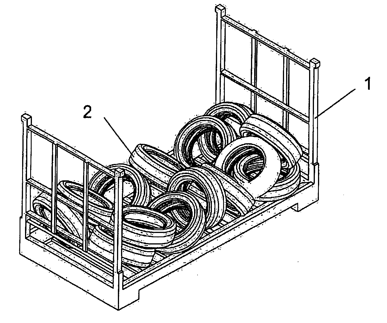
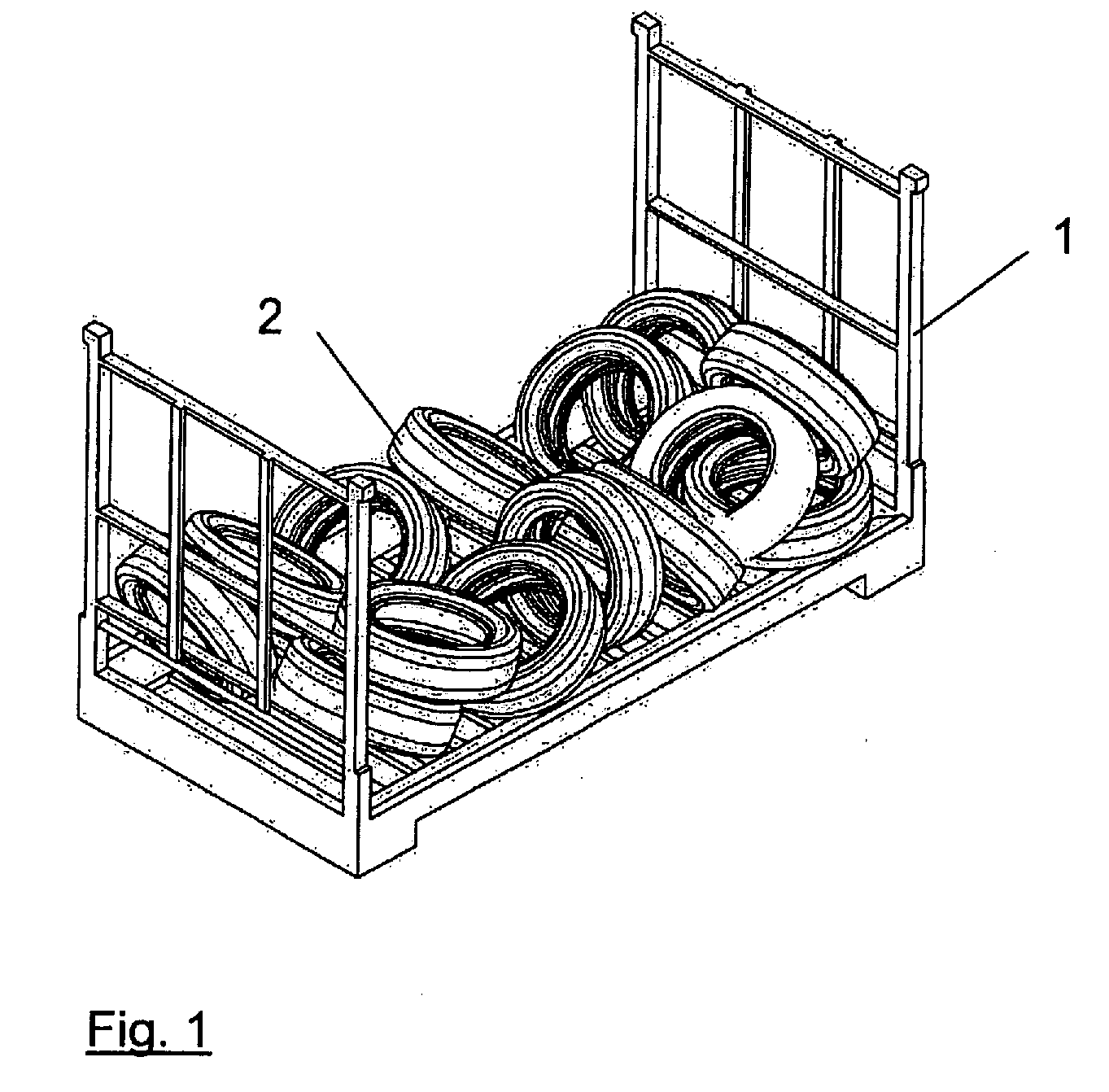
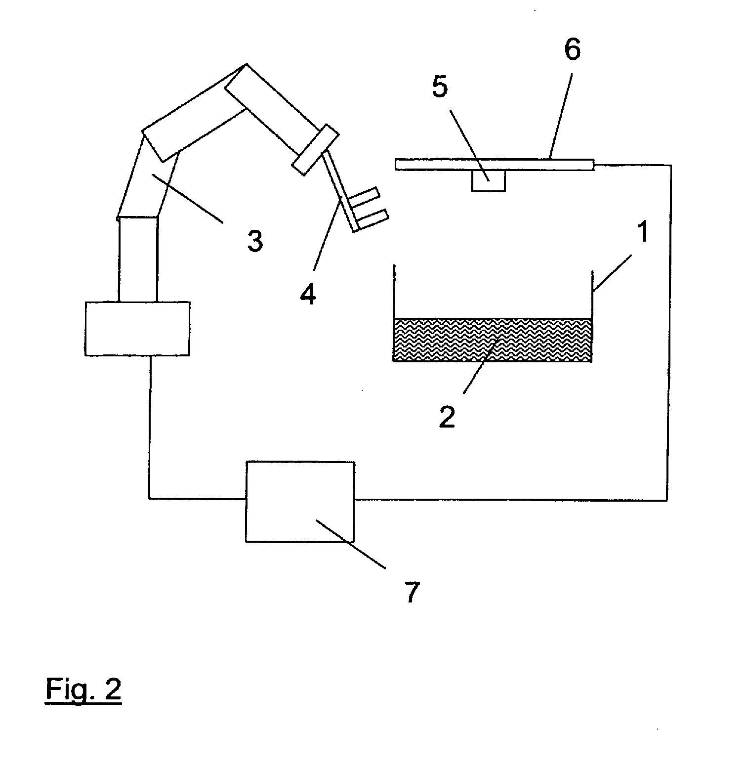
[0026]The depalletizing method and the associated depalletizing system according to the invention enable the automatic unloading of tires that are stacked on a transport unit with a robot (in particular a 6-axis articulated arm robot). In this regard FIG. 1 shows an example of a transport unit 1 on which are stacked multiple tires 2 (unorganized in the present case). Such a transport unit 1 is normally placed in an unloading region with a floor conveyor apparatus, for example a forklift or a lift trick. In the proposed method, such a transport unit 1 is unloaded with a depalletizing system as it is shown by way of example in FIG. 2.

[0027]FIG. 2 shows an exemplary depalletizing system according to the present invention in a significantly schematized presentation. The depalletizing system has a 6-axis articulated arm robot 3 with a gripper 4 that is coupled via a connection flange to the arm of the articulated arm robot 3. A linear axle 6 that bears a 3D sensor 5 is arranged above the...


PUM


Abstract

In a method and system for depalletizing tires using a robot, wherein the tires are randomly located on a carrier, the position and orientation of outer tires on the carrier are detected using a sensor, and a processor, using a signal from the sensor, determines a tire that can be gripped by a gripping tool of an industrial robot, and calculates a movement path for the gripping tool for that tire. If the calculated path is not collision-free, another tire from among the outer tires is selected, and a movement path for depalletizing that tire is determined. The procedure is repeated until a collision-free movement path for a tire from among the outer tires is established. The gripping tool is then guided according to this collision-free movement path to depalletize the tire having the collision-free path associated therewith.

Description

FIELD OF THE INVENTION[0001]The present invention concerns a method and a system for robot-directed depalletizing tires that are stored on a carrier.DESCRIPTION OF THE PRIOR ART[0002]The depalletizing tires are understood as the unloading of tires from a transport unit or a loading carrier, for example unloading from a container or from a grid pallet. In general, the spectrum of stacking patterns of the tires in their delivery ranges from organized to semi-organized to unorganized or chaotic. The unloading of tires is presently executed exclusively by hand in the case of partially organized or unorganized orientation of the tires on the loading carrier.[0003]In most cases the palletizing of tires has also previously been conducted by hand. However, an automatic solution to stack tires on a carrier is known from DE 10 2005053 296 A1. However, even given a precise knowledge of the depositing position during the palletizing, an automatic unloading of the tires has still not always prev...

Claims


Application Information

Patent Timeline
Patent Type & Authority Applications(United States)
IPC IPC(8): B65G65/00G06F19/00B25J9/16
CPCB25J9/1697B65G61/00G05B2219/40053G05B2219/39484G05B2219/39536B65G2201/0273
Inventor COTTONE, NORBERTEBERHARDT, THORSTENHEISSMEYER, SVENHOLLINGER, ALEXANDERPEGHINI, MARTIN
Owner KUKA ROBOTER
Learn More