
Determination of one or more gearshift points

Active Publication Date: 2012-06-28
SCANIA CV AB
View PDF12 Cites 4 Cited by
  • Summary
  • Abstract
  • Description
  • Claims
  • Application Information

AI Technical Summary

Benefits of technology

[0016]A method and a system according to the invention result in a flexible and more exact determination of the one or more downshift and upshift points. The fact that the shift points are determined on the basis of a change in road gradient makes it possible for them to be determined so that they are adjusted to both current and future running resistances to the vehicle. The settings of the one or more downshift and upshift points can thereby be optimised so that fuel consumption decreases and running characteristics are improved.

Problems solved by technology

This procedure for calibration of shift points is both time-consuming and expensive.
Moreover, the results of the calibration are not always satisfactory in that the calibrated shift points may be appropriate for certain driving situations but less so for others.
In certain driving situations, particularly if basic conditions change, the previously known methods for choice of shift points therefore result in non-optimum running characteristics.

Method used


Image

  • Determination of one or more gearshift points
  • Determination of one or more gearshift points
  • Determination of one or more gearshift points

Examples


Embodiment Construction

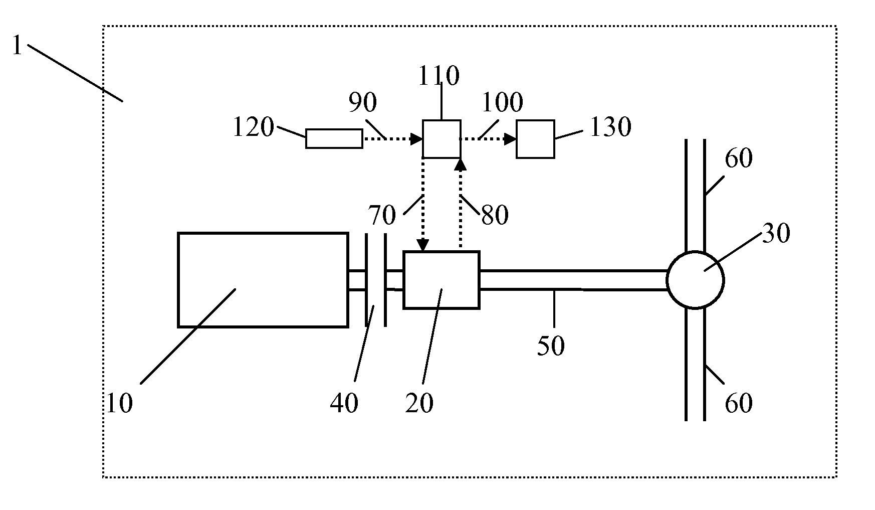
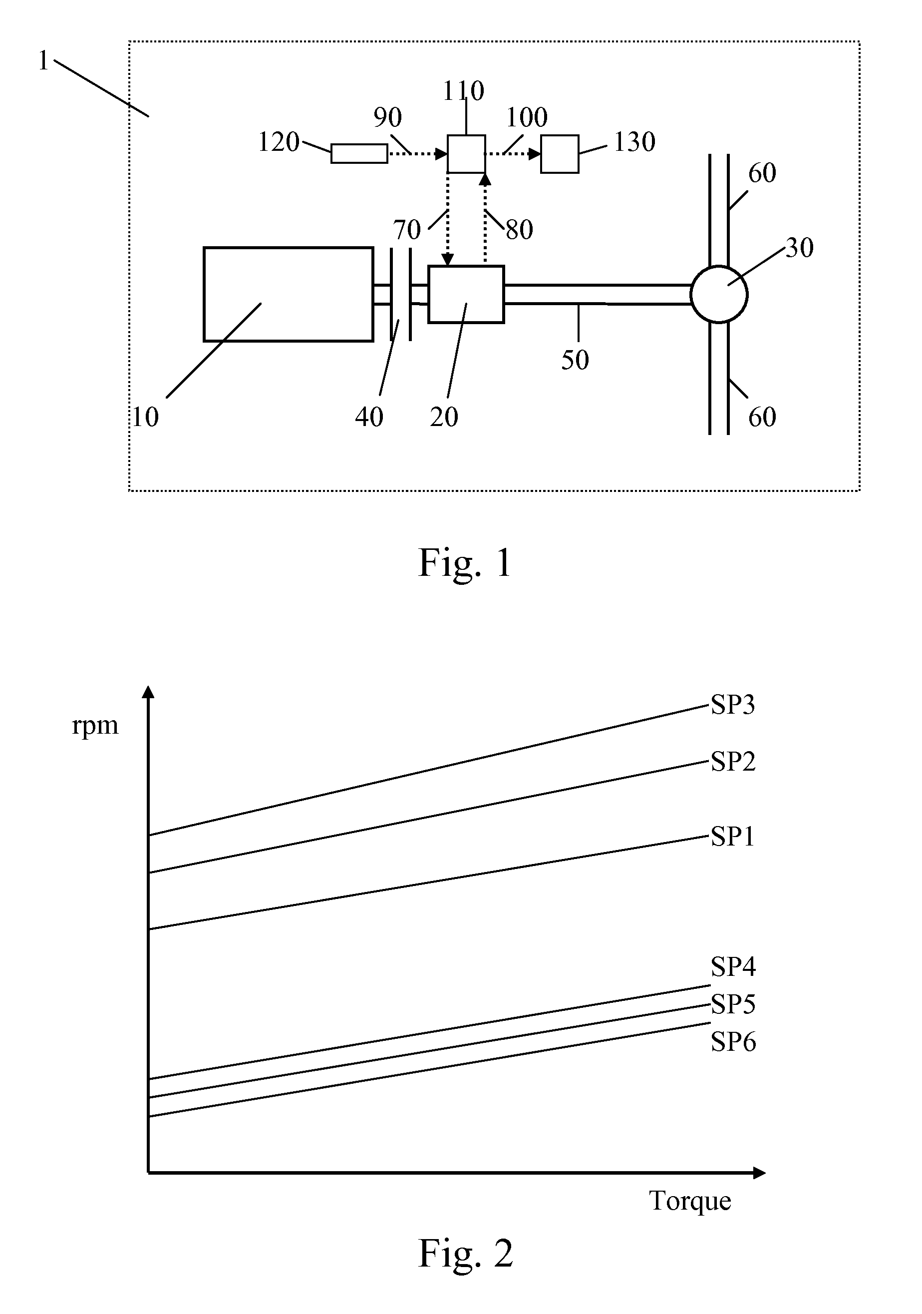
[0023]The present invention relates to determination of one or more shift points for a gearbox 20 situated preferably in a motor vehicle 1. A downshift or upshift represents an engine speed at which the gearbox 20 is respectively adapted to effecting a downshift or upshift. The engine speed for upshift points is higher than the engine speed for downshift points. As indicated above, the shift points comprise information both about when, i.e. at what engine speed and torque, a downshift or upshift should take place and about how many gear steps should be taken at each downshift or upshift.

[0024]The gearbox 20 is preferably of the kind which forms part of an automated gearbox system controlled by a control unit 110, e.g. an ECU. In such a system, gear changes are effected automatically by the control unit 110 but there are also systems whereby the driver can execute manual gear changes in such an automatic gear system, what is known as manual gear change in automatic state (automatic m...


PUM


Abstract

A method, a system, a computer program and a computer program product for determining one or more shift points for a gearbox in a motor vehicle which comprises an engine connected to, in order to drive the gearbox. A shift point is defined by an engine speed at which the gearbox effects a downshift or upshift. The method uses one or more shift points determined on the basis of a change in road gradient.

Description

TECHNICAL FIELD[0001]The present invention relates to a method for determination of one or more shift points for a gearbox in a motor vehicle. In particular, the invention relates to a method according to the preamble of claim 1. The invention further relates to a system according to the preamble of claim 14, a motor vehicle which comprises the system according to the invention, and a computer programme and a computer programme product which implement the method according to the invention.BACKGROUND TO THE INVENTION[0002]FIG. 1 depicts schematically parts of a power train for a motor vehicle 1, such as a passenger car or a heavy vehicle, e.g. a truck or bus. The power train comprises an engine 10 mechanically connected by a shaft to a first end of a gearbox 20 via a clutch device 40. The gearbox 20 is also mechanically connected, at its other end, by a propeller shaft 50 to a differential gear 30 associated with a rear axle. The rear axle comprises respective left and right drive sh...

Claims


Application Information

Patent Timeline
IPC IPC(8): F16H59/66
CPCF16H2059/663Y10T477/65F16H2059/366F16H59/66F16H61/0213B60W2552/15
Inventor SWARTLING, FREDRIKWAGBERG, MIKAELOUN, MIKAEL
Owner SCANIA CV AB
Learn More