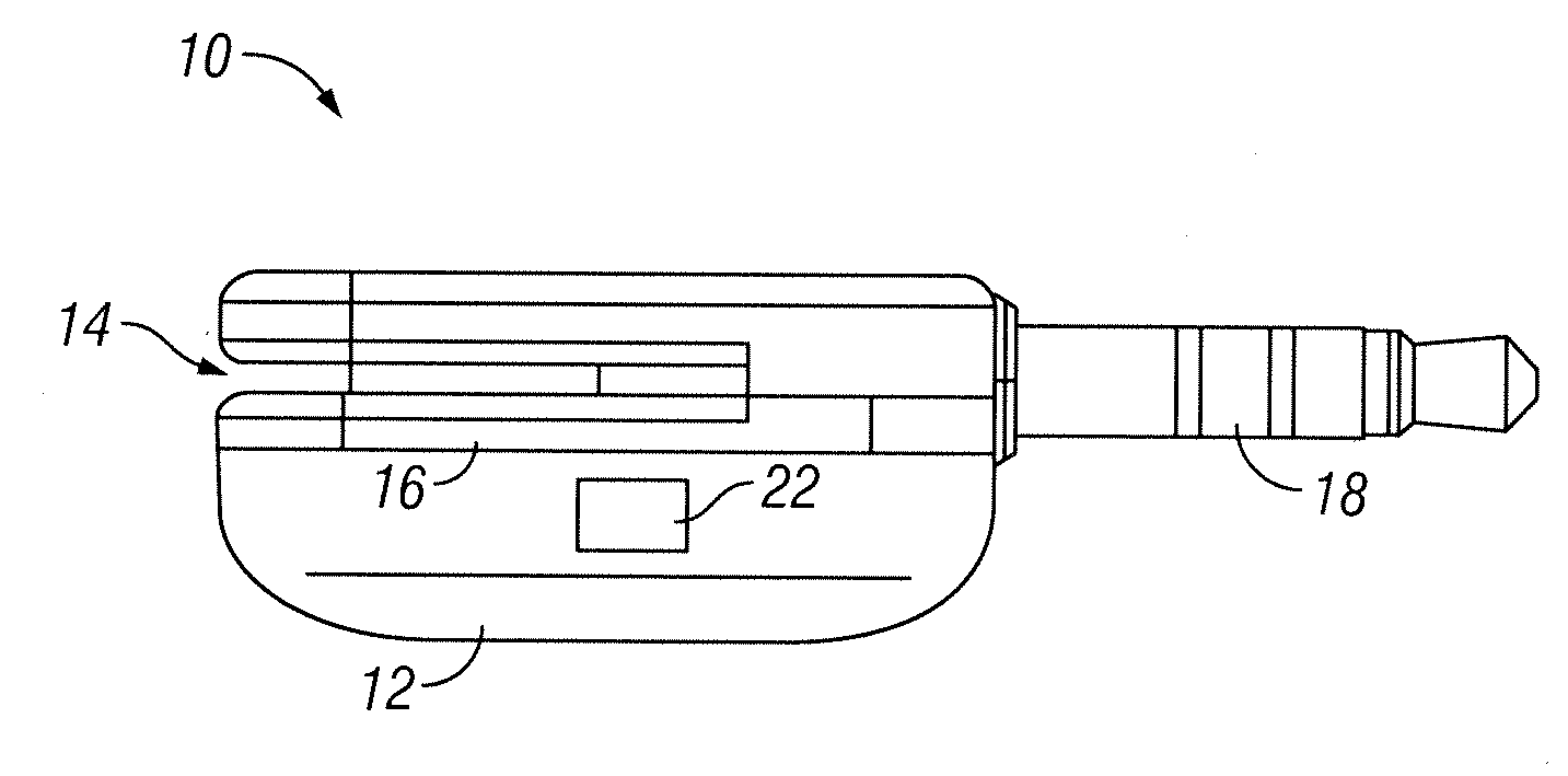
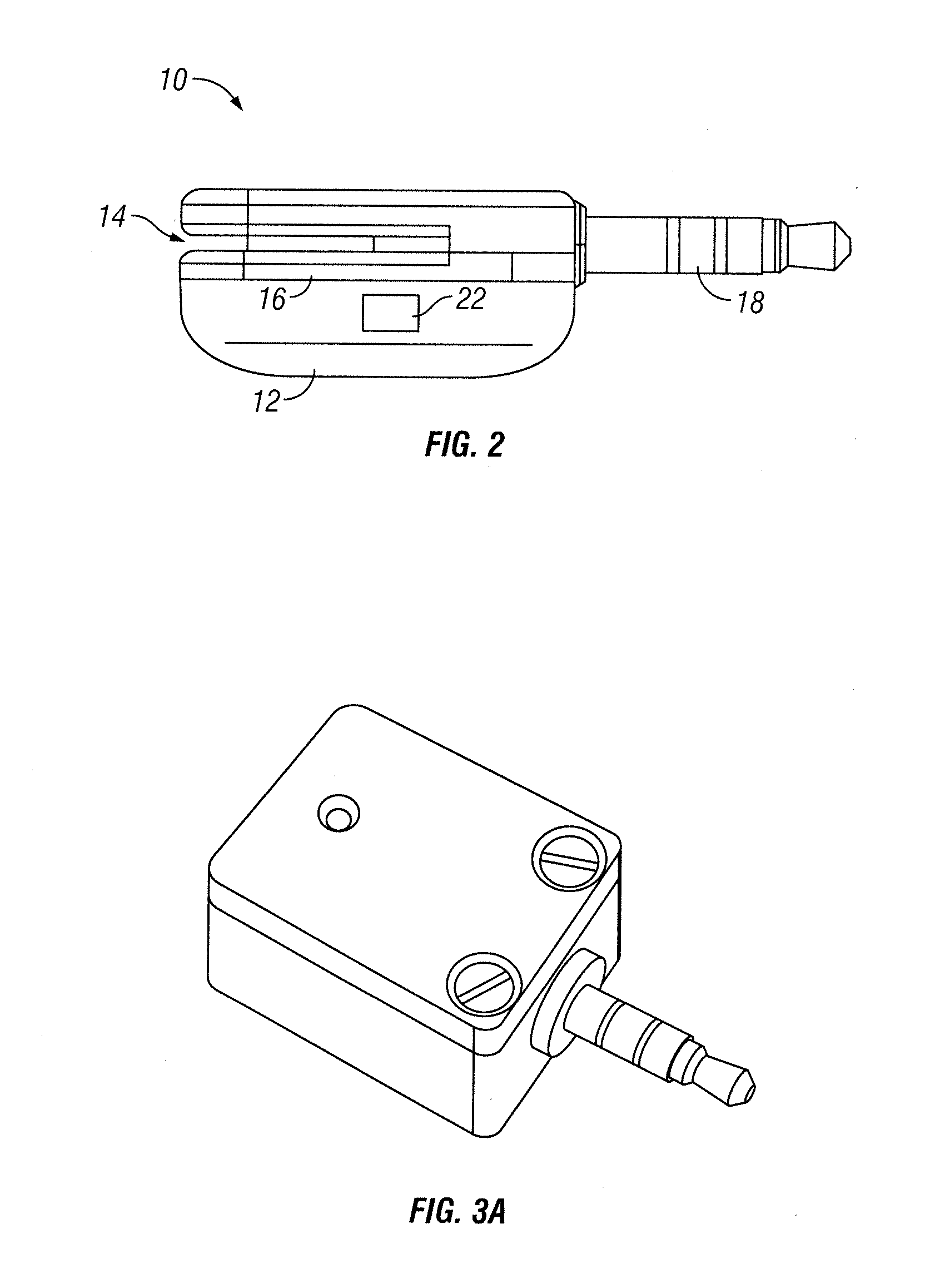
Card reader with asymmetric spring
a card reader and asymmetric spring technology, applied in the field of card readers, can solve the problem of no way for an individual to take advantage of the card, and achieve the effect of increasing the efficiency of financial transactions
- Summary
- Abstract
- Description
- Claims
- Application Information
AI Technical Summary
Benefits of technology
Problems solved by technology
Method used
Image

Examples
Embodiment Construction
[0063]The approach is illustrated by way of example and not by way of limitation in the figures of the accompanying drawings in which like references indicate similar elements. It should be noted that references to “an” or “one” or “some” embodiment(s) in this disclosure are not necessarily to the same embodiment, and such references mean at least one.
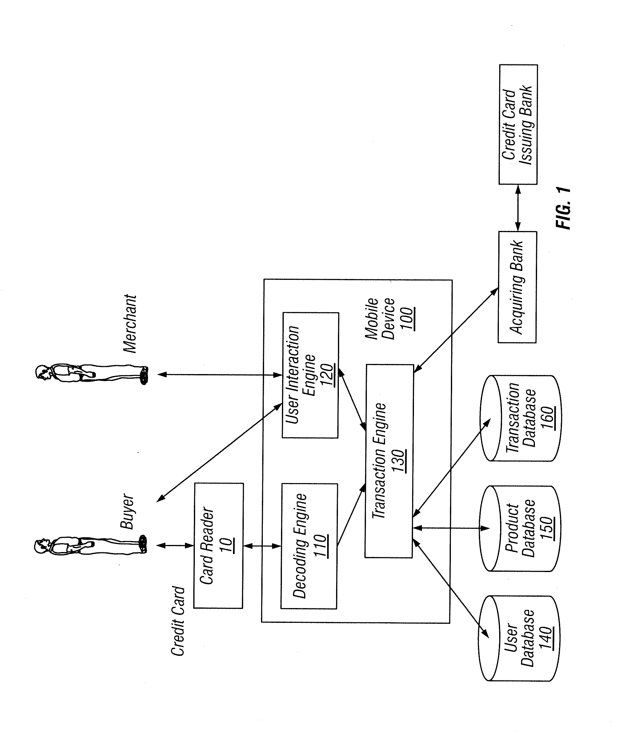
[0064]FIG. 1 depicts an example of a system diagram to support financial transaction between a payer and a payee through a miniaturized card reader connected to a mobile device. Although the diagrams depict components as functionally separate, such depiction is merely for illustrative purposes. It will be apparent that the components portrayed in this figure can be arbitrarily combined or divided into separate software, firmware and / or hardware components. Furthermore, it will also be apparent that such components, regardless of how they are combined or divided, can execute on the same host or multiple hosts, and wherein multiple hosts...
PUM
 Abstract
Description
Claims
Application Information
 - Generate Ideas
- Intellectual Property
- Life Sciences
- Materials
- Tech Scout
- Unparalleled Data Quality
- Higher Quality Content
- 60% Fewer Hallucinations
Browse by: Latest US Patents, China's latest patents, Technical Efficacy Thesaurus, Application Domain, Technology Topic, Popular Technical Reports.
© 2025 PatSnap. All rights reserved.Legal|Privacy policy|Modern Slavery Act Transparency Statement|Sitemap|About US| Contact US: help@patsnap.com