Proton engine

a proton engine and engine technology, applied in generators/motors, nuclear power plants, nuclear engineering, etc., can solve the problems of inconvenient emission and large energy of individual atomic nuclei, and achieve the effect of high speed

Pending Publication Date: 2012-07-05
ROSS
View PDF0 Cites 0 Cited by
  • Summary
  • Abstract
  • Description
  • Claims
  • Application Information

AI Technical Summary

Problems solved by technology

Traditional combustion releases energy by breaking down molecular chemical bonds, which results in inconvenient emissions and leaves the large energy of individual atomic nuclei untapped.

Method used


Image

  • Proton engine
  • Proton engine
  • Proton engine

Examples


Embodiment Construction

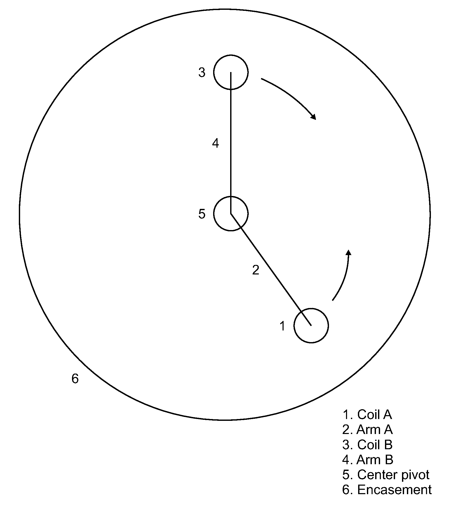
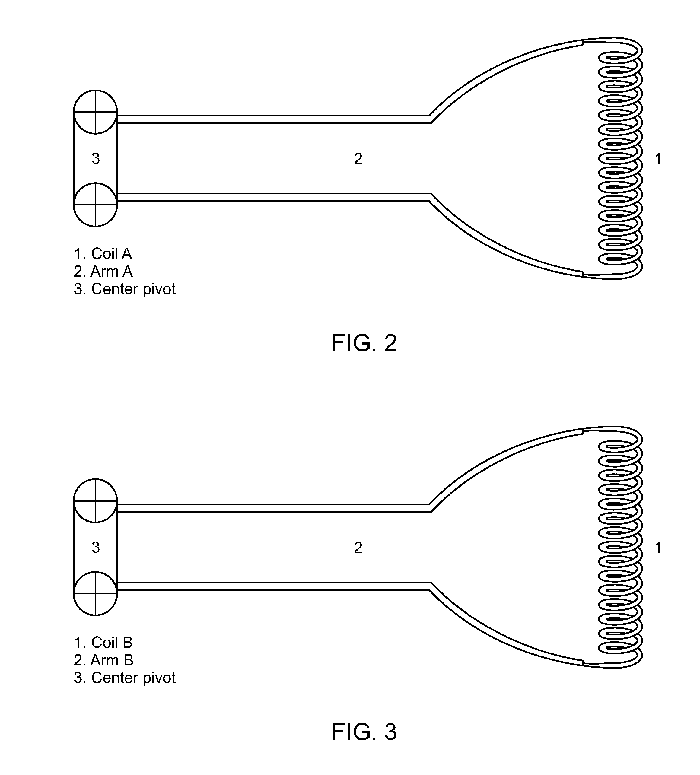
[0019]The present disclosure relates generally to a power generation system which unlocks the energy of particles by driving them at a high rate of speed into a magnetic field. The required high rate of speed will vary depending. on the size of machine, amount of energy to be produced, and other variables. In any event, it should be a speed sufficient to destroy the particles within the environment of the particular device. The precise speed required for a given device can be fine-tuned by one skilled in the art.

[0020]According to the Lorentz force law, a particle carrying 1 coulomb of charge and passing through a magnetic field of 1 tesla at a speed of 1 meter per second, experiences a force of 1 newton. By increasing the speed at which a particle passes through a magnetic field, the force the particle experiences will increase accordingly.

[0021]By holding the particles in place with an additional magnetic field and adjusting the angle at which they strike the primary magnetic fiel...


PUM


Abstract

A power generation device that converts matter into energy. A solenoid is rotated circumferentially at high speed clockwise or counter-clockwise. A coiled semi-conductor tube of similar size, which contains charged particles in gas or plasma form is rotated at high speed in the opposite direction. The hollow coil is wrapped in a conducting coil that creates a magnetic field inside it, holding the particles in place as an RF coil injects a resonant frequency to align the spins of the particles. The particles are driven at a high rate of speed into the solenoid's Magnetic field. The resulting energy output is collected.

Description

CROSS-REFERENCES TO RELATED APPLICATIONS[0001]This application claims priority from U.S. application No. 61 / 460,364, filed Dec. 30, 2010 and which is incorporated by reference in its entirety.BACKGROUND[0002]The present invention relates to power generation. The equation E=mc2 implies that a large amount of energy is locked up inside fermionic matter. Traditional combustion releases energy by breaking down molecular chemical bonds, which results in inconvenient emissions and leaves the large energy of individual atomic nuclei untapped.[0003]Free neutrons exist only a short time before they decay (approximately 15 minutes). Neutrons are composed of three quarks, one ‘up quark’ and two ‘down quarks’. In neutron beta decay one of the two ‘down quarks’ switches to an ‘up quark’, emitting an electron and a neutrino. The remaining proton is left with two ‘up quarks’ and one ‘down quark’. The present invention aims at the remaining ‘down quark’ or either one of the remaining ‘up quarks’ to...

Claims


Application Information

Patent Timeline
Patent Type & Authority Applications(United States)
IPC IPC(8): G21G1/10
CPCG21D7/00G21G7/00H02N11/002G21G1/10
Inventor ROSS, OWEN VENMORE
Owner ROSS
Why Eureka
Try Eureka