Dynamic adaptive respiration compensation with automatic gain control

a technology of automatic gain control and adaptive respiration compensation, which is applied in the field of dynamic adaptive respiration compensation with automatic gain control, can solve problems such as reducing compensation signals, and achieve the effect of reducing unwanted interferen

Active Publication Date: 2012-07-05
ST JUDE MEDICAL ATRIAL FIBRILLATION DIV
View PDF14 Cites 81 Cited by
  • Summary
  • Abstract
  • Description
  • Claims
  • Application Information

AI Technical Summary

Benefits of technology

[0010]One advantage of the methods and apparatus described, depicted and claimed herein involves the ability to provide respiration or other motion (e.g., cardiac activity) compensation for a localization system throughout the duration of an electrophysiological (EP) study or the like despite changing respiration patterns and despite movements of the catheter to different locations in the heart. In addition, an automatic gain control feature mitigates against unwanted interferences introduced by body surface electrode (patch) noise or sudden changes in patch impedance.
[0012]The step of acquiring a new set of weights involves, in an embodiment, principal component analysis (PCA) and singular value decomposition (SVD). In addition, the step of updating the reference set of weights involves the use of a learning parameter. The value of the learning parameter is variable and determines how rapidly the reference set of weights (i.e., the set of weights actually used to compute the compensation signal) is adjusted to changes that occur in the new (acquired) set of weights (i.e., the weights computed based on the new patch impedances and electrode location data). A low value for the learning parameter means that the reference set of weights will adapt slowly, while a higher value for the learning parameter means that the reference set of weights will be adjusted aggressively in the direction of the new weights. The learning parameter, in turn, is varied based on a computed “distance” between successive, acquired sets of weights. The “distance” is used to detect when a clinician has intentionally moved the catheter during the calculation of weights, during which dynamic adaptation is suppressed. In addition, the magnitude of the calculated compensation signal may itself be suppressed in accordance with a gain parameter (i.e., an automatic compensation gain control feature). The gain control feature detects when sudden changes occur in the patch impedance data, indicative of noise or the like. In an embodiment, statistical analysis is used to determine when a change constitutes a “sudden” change sufficient to invoke suppression. When such a condition is detected, the gain control feature reduces the gain parameter, thereby reducing the compensation signal.

Problems solved by technology

When such a condition is detected, the gain control feature reduces the gain parameter, thereby reducing the compensation signal.

Method used


Image

  • Dynamic adaptive respiration compensation with automatic gain control
  • Dynamic adaptive respiration compensation with automatic gain control
  • Dynamic adaptive respiration compensation with automatic gain control

Examples


Embodiment Construction

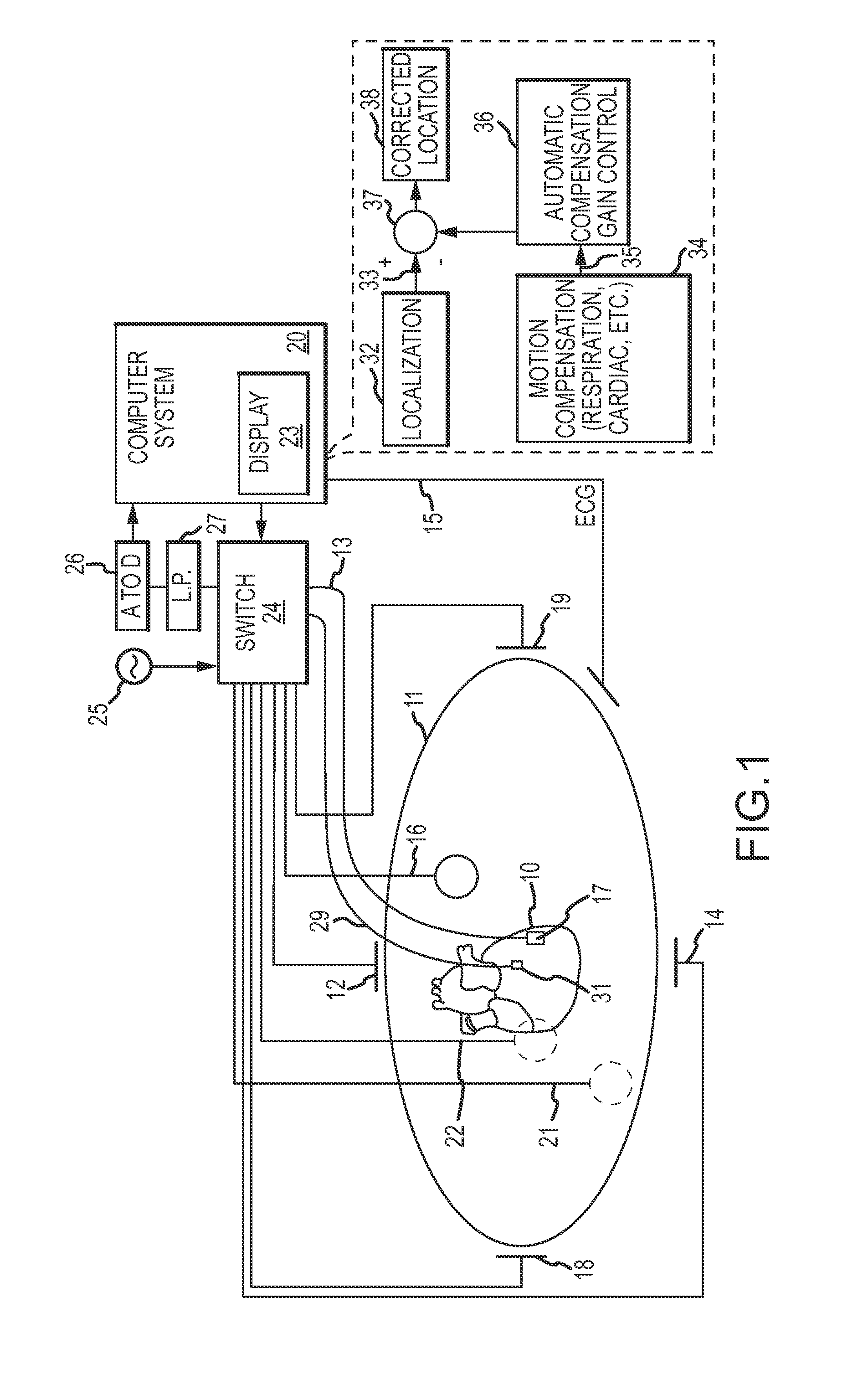
[0035]Referring now to the drawings wherein like reference numerals are used to identify identical components in the various views, FIG. 1 is a diagrammatic overview of a catheter system in which the present invention may be practiced. The system may comprise various visualization, mapping and navigation components as known in the art, including among others, for example, an EnSite™ Electro Anatomical Mapping System commercially available from St. Jude Medical, Inc., or as seen generally by reference to U.S. Pat. No. 7,263,397 entitled “METHOD AND APPARATUS FOR CATHETER NAVIGATION AND LOCATION AND MAPPING IN THE HEART” to Hauck et al., or U.S. Patent Publication No. 2007 / 0060833 A1 to Hauck entitled METHOD OF SCALING NAVIGATION SIGNALS TO ACCOUNT FOR IMPEDANCE DRIFT IN TISSUE, both owned by the common assignee of the present invention, and both hereby incorporated by reference in their entireties. The system may be used in connection with or for various medical procedures, for examp...


PUM


Abstract

A system for determining a location of an electrode of a medical device (e.g., a catheter) in a body of a patient includes a localization block for producing an uncompensated electrode location, a motion compensation block for producing a compensation signal (i.e., for respiration, cardiac, etc.), and a mechanism for subtracting the compensation signal from the uncompensated electrode location. The result is a corrected electrode location substantially free of respiration and cardiac artifacts. The motion compensation block includes a dynamic adaptation feature which accounts for changes in a patient's respiration patterns as well as intentional movements of the medical device to different locations within the patient's body. The system further includes an automatic compensation gain control which suppresses compensation when certain conditions, such as noise or sudden patch impedance changes, are detected.

Description

CROSS-REFERENCE TO RELATED APPLICATIONS[0001]Not applicable.BACKGROUND OF THE INVENTION[0002]a. Field of the Invention[0003]The instant invention relates generally to localization systems for determining position utilizing localization fields and more particularly to a localization system having dynamic adaptive respiration compensation with automatic gain control.[0004]b. Background Art[0005]Numerous technologies have been developed to permit the determination of the location of a catheter inside of a beating heart. U.S. Pat. No. 5,697,377 to Wittkampf discloses a system that uses orthogonal currents (i.e., along three axes—X, Y and Z) injected into the body using body surface electrodes (patches) to localize the catheter. In Wittkampf's system, an electrode located on the catheter measures voltages arising from the three injected currents, which are then processed to resolve the X, Y and Z axis coordinates defining the position of the electrode and hence also the position of the c...

Claims


Application Information

Patent Timeline
Patent Type & Authority Applications(United States)
IPC IPC(8): A61B5/05
CPCA61B5/053A61B5/061H04L25/03019A61B5/7207A61B5/721H04L25/0278A61B5/0044A61B5/0536A61B5/0538A61B5/06A61B5/063A61B5/6801A61B5/7203A61B5/7267A61B5/742
Inventor KOYRAKH, LEV A.VOTH, ERIC J.HAUCK, JOHN A.SCHWEITZER, JEFFREY A.
Owner ST JUDE MEDICAL ATRIAL FIBRILLATION DIV
Why Eureka
Try Eureka