Automatic identification of intracardiac devices and structures in an intracardiac echo catheter image

an intracardiac echo and catheter image technology, applied in the field of medical imaging and physiologic modeling, can solve the problems of all imaging modalities, introduce uncertainty, and medical images are useful, and achieve the effect of accurate model and easy navigation of ice catheters and other ep devices

Inactive Publication Date: 2012-07-05
ST JUDE MEDICAL ATRIAL FIBRILLATION DIV
View PDF13 Cites 51 Cited by
  • Summary
  • Abstract
  • Description
  • Claims
  • Application Information

AI Technical Summary

Benefits of technology

[0009]Display of a tracked EP device within an ICE echo image allows the clinician to more easily navigate both the ICE catheter and other EP devices. A tracked EP device can have its position relative to the ICE echo plane calculated if the position of the ICE catheter within a geometric model maintained by the visualization, navigation, or mapping system is known. Any tracked EP device falling within or sufficiently close to the echo plane can then be displayed in the ICE image by a variety of visual identifiers.
[0010]The combination of ICE echo imaging information with structures from the geometric model allows the clinician to verify the position and structure of physical features and to identify errors in the geometric model. By projecting sectional representations from the geometric model into the ICE echo image discrepancies can be identified and corrected within the geometric model, thereby creating a more accurate model. Feature geometries from the geometric model projected into the ICE image are created by calculating the echo plane cross section of the feature and displaying the cross section boundaries within the ICE image. The portion of the ICE image falling within the cross sectional boundaries can then be segmented to separate tissue structures from voids, and the boundaries of the voids can then be displayed within the geometric model. By combining multiple segmented echo plane geometries a more complete model of the heart chamber can be acquired. The segmented chamber boundaries can also be used to create local deformations or modifications to the geometric model.

Problems solved by technology

However, all imaging modalities suffer from some type of error that introduces uncertainty into the resulting images.
Further limiting the usefulness of medical images is the difficulty in interpreting the content of an image when the image contains no identifiable landmarks to provide context.
Without a landmark to locate an image within the body the content of the image can often be of limited use.
However, visual identification of another intracardiac catheter in the echo image often is not sufficient to locate the ICE catheter and does not allow the accurate combination of an ICE echo image and a geometric model created with electric or magnetic field modeling.
However, electrical navigational fields are not assured to be homogeneous or isotropic, so it is common for these geometric models to suffer from distortion.
Further complicating the location of ICE catheters and the images they produce is the fact that the echo images often are not representative of the idealized echo plane, as it has been observed that the echo image commonly suffers from both rotational and translational deviations from the ideal.

Method used


Image

  • Automatic identification of intracardiac devices and structures in an intracardiac echo catheter image
  • Automatic identification of intracardiac devices and structures in an intracardiac echo catheter image
  • Automatic identification of intracardiac devices and structures in an intracardiac echo catheter image

Examples


Embodiment Construction

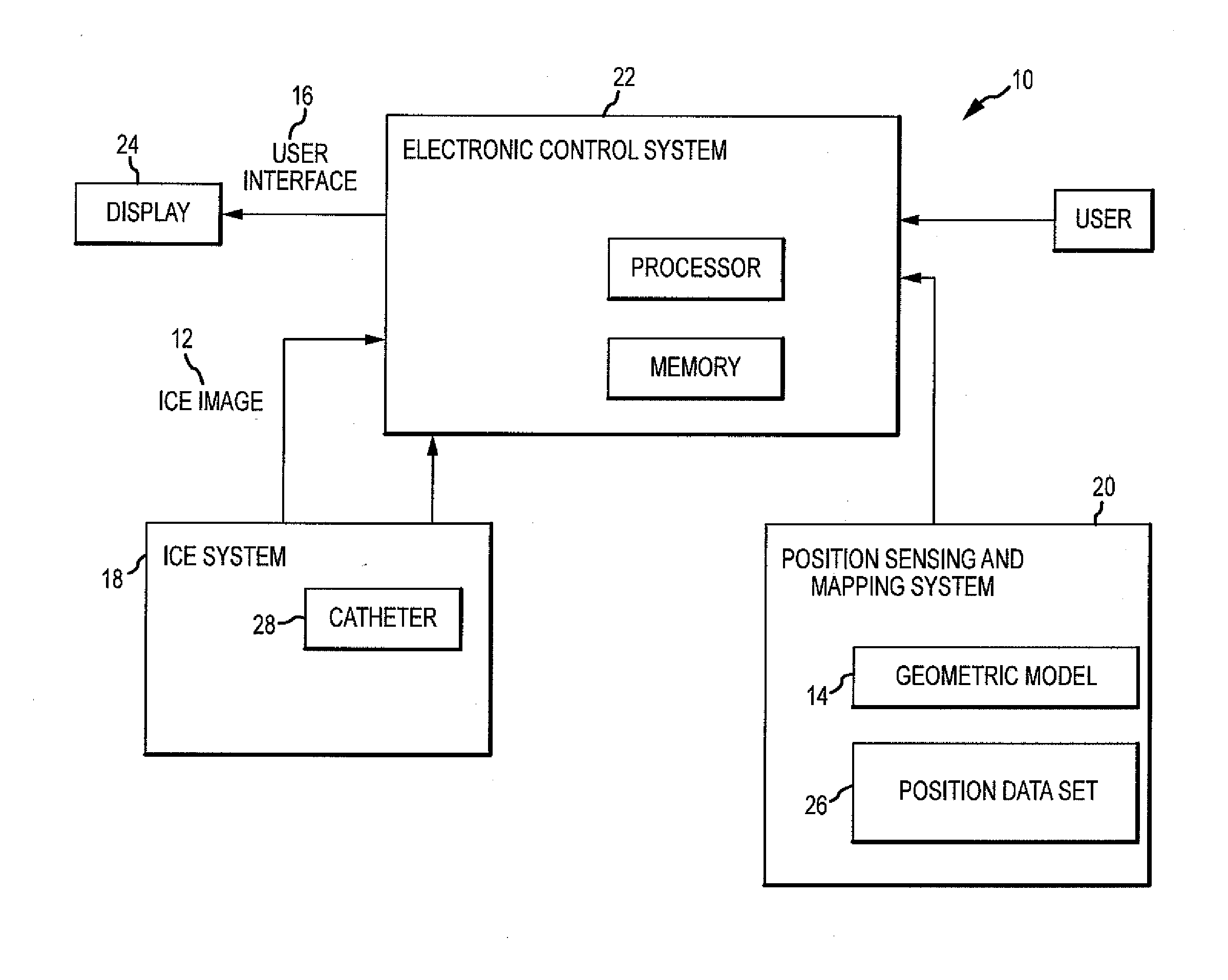
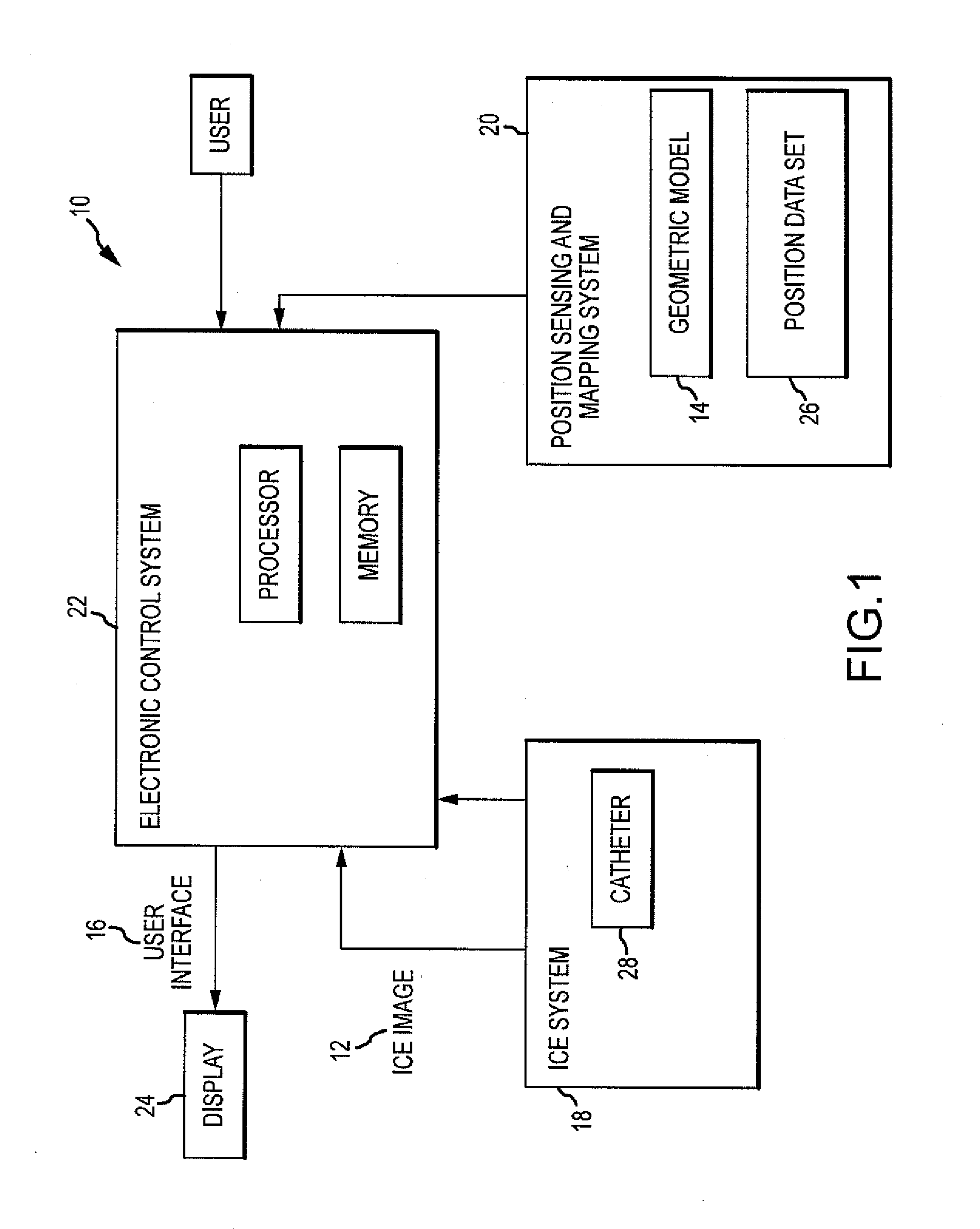
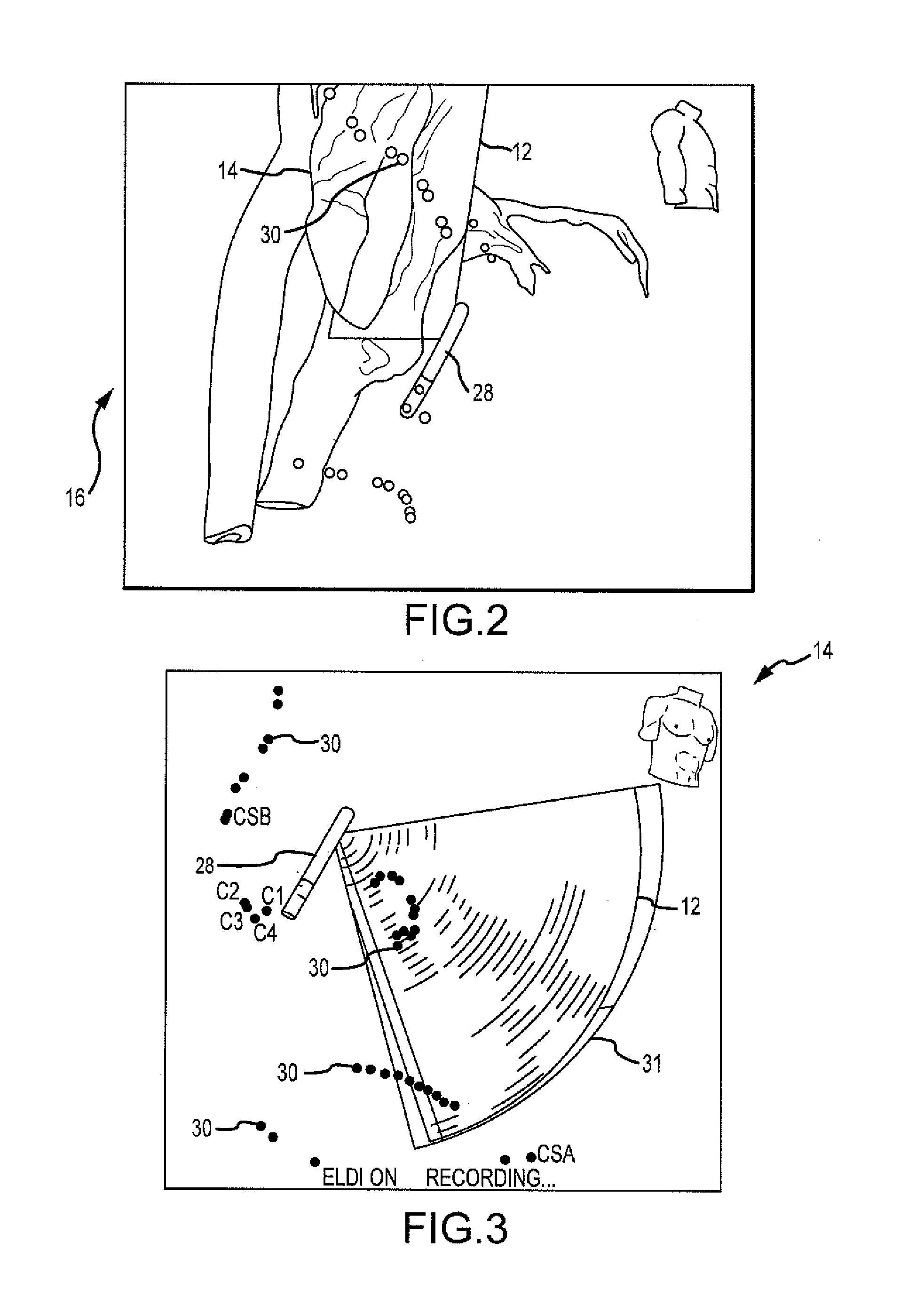
[0020]Referring now to the drawings wherein like reference numerals are used to identify identical components in the various views, FIG. 1 illustrates one exemplary embodiment of a system 10 configured to display within an intracardiac echocardiography image 12 (ICE image) devices present within a geometric model 14 of the heart and to auto-segment the ICE image 12 to generate one or more shell elements 36. The system 10 being further configured to generate a user interface 16 for displaying the ICE image 12 and the geometric model 14 as well as to receive user input directing the control and operation of the system 10.

[0021]The system 10 according to an embodiment of the present disclosure comprises an intracardiac echo imaging system 18 (ICE system), a visualization, navigation, or mapping system 20 (“VNM” system), an electronic control system (ECS) 22, and a display 24. The ECS 22 may be configured to receive an ICE image 12 produced by the ICE system 18 and the ECS 22 may furthe...


PUM


Abstract

An intracardiac imaging system configured to display electrode visualization elements within an intracardiac echocardiography image where the electrode visualization elements represent intracardiac electrodes in close proximity to the plane of the image. The system further allows cross sections of tissue structures embodied in intracardiac echocardiography images to be modeled within a visualization, navigation, or mapping system when automatically segmented to generate shell elements for modifying the modeled tissue structures.

Description

BACKGROUND OF THE INVENTION[0001]a. Field of the Invention[0002]The present invention relates to medical imaging and physiologic modeling, and particularly, the present invention relates to the identification and tracking of devices and structures within one imaging or modeling modality and the concurrent display of that information within a separate imaging or modeling modality.[0003]b. Background Art[0004]It is well known that the prevalence of different imaging modalities in medicine provide the clinician with valuable information regarding patient physiology. However, all imaging modalities suffer from some type of error that introduces uncertainty into the resulting images. Further limiting the usefulness of medical images is the difficulty in interpreting the content of an image when the image contains no identifiable landmarks to provide context. Without a landmark to locate an image within the body the content of the image can often be of limited use.[0005]It is well known t...

Claims


Application Information

Patent Timeline
Patent Type & Authority Applications(United States)
IPC IPC(8): A61B8/14
CPCA61B8/0841A61B8/12G06T2210/41A61B8/5253G06T19/00A61B8/461A61B8/0883A61B8/4245A61B8/463A61B8/5246
Inventor HILL, ANTHONY D.DENO, D. CURTISZHONG, HUAGRASSE, MARTIN M.
Owner ST JUDE MEDICAL ATRIAL FIBRILLATION DIV
Why Eureka
Try Eureka