Rotational Atherectomy Device with Fluid Inflatable Support Elements and Two Torque Transmitting Coils

a technology of atherectomy device and support element, which is applied in the field of rotational atherectomy device, can solve the problems of difficult manufacturing on a commercial scale, complex construction, and potential life-threatening complications

Inactive Publication Date: 2012-07-05
CARDIOFLOW
View PDF0 Cites 21 Cited by
  • Summary
  • Abstract
  • Description
  • Claims
  • Application Information

AI Technical Summary

Benefits of technology

[0040]In one embodiment of the invention, the torque transmitting coils are disposed coaxially with respect to each other, one of two coils being an inner torque transmitting coil and the other torque transmitting coil being an outer torque transmitting coil, the inner and the outer torque transmitting coils being wound in opposite directions so that, when the drive shaft is rotated, the outer torque transmitting coil prevents unwinding of the inner torque transmitting coil.
[0043]In one embodiment, a valve is formed at the distal end of the drive shaft. Preferably, the drive shaft may comprise a radially inwardly extending shoulder located at or just proximal to the distal end of the drive shaft. In this embodiment, the device may also comprise a rounded element configured to be advanced to a distal end of the drive shaft where it is prevented from exiting the drive shaft by the radially inwardly extending shoulder, thereby occluding the distal end of the drive shaft and thereby at least partially preventing flow of fluid through the very distal end of the drive shaft and assisting in the redirection of the flow of fluid into the fluid inflatable support elements. The radially inwardly extending shoulder can be formed integrally with a distal end of the inner torque transmitting coil.

Problems solved by technology

Clearly, the existence of particulate matter in the blood stream is undesirable and can cause potentially life-threatening complications, especially if the particles are over a certain size.
The rotational atherectomy device known from U.S. Pat. No. 5,681,336 (to Clement et al.) has a complicated construction and is difficult to manufacture on a commercial scale.
An atherectomy device having this design allows excellent transmission of torque to the abrasive element by the torque transmitting coil, but does not enable the device to have a sufficiently small transverse cross-sectional dimension to cross very tight stenotic lesions.

Method used


Image

  • Rotational Atherectomy Device with Fluid Inflatable Support Elements and Two Torque Transmitting Coils
  • Rotational Atherectomy Device with Fluid Inflatable Support Elements and Two Torque Transmitting Coils
  • Rotational Atherectomy Device with Fluid Inflatable Support Elements and Two Torque Transmitting Coils

Examples


Embodiment Construction

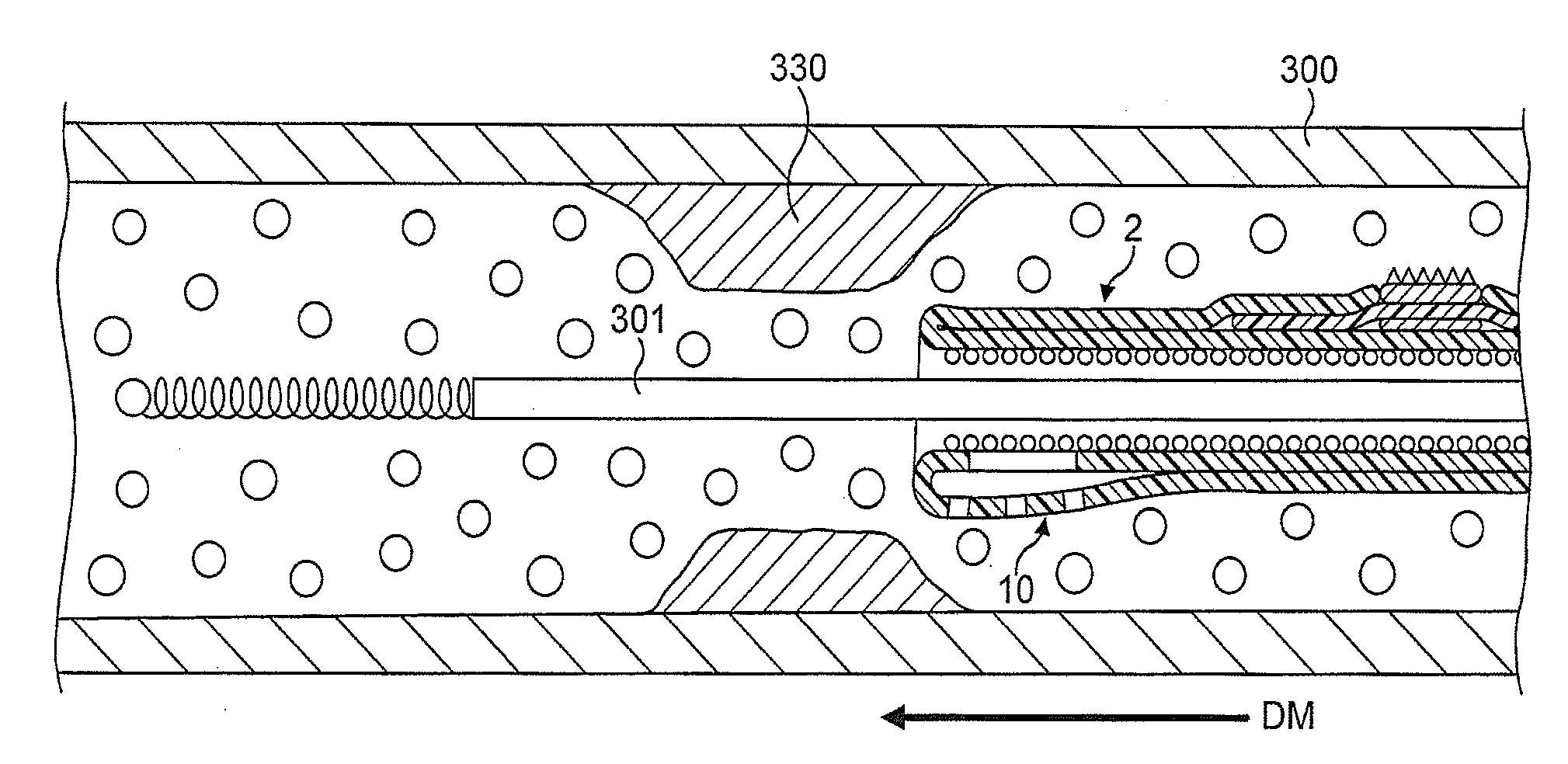
[0084]In FIGS. 1 to 64, the atherectomy device is advanced across the stenotic lesion 330 over the guidewire 301. The direction of movement of the device is indicated by arrow marked “DM”, the antegrade flow of fluid being indicated by arrows “FF” and the flow of fluid in a retrograde direction is indicated by arrows marked “R”. Arrows marked “FP” designate pressure of fluid which distends the support elements. Abraded particles AP abraded from the stenotic lesion 330 are aspirated into a lumen of a drive shaft sheath 5000 so that the retrograde flowing fluid and the abraded particles entrained in said fluid can be removed from the treated vessel and out of the patient's body.

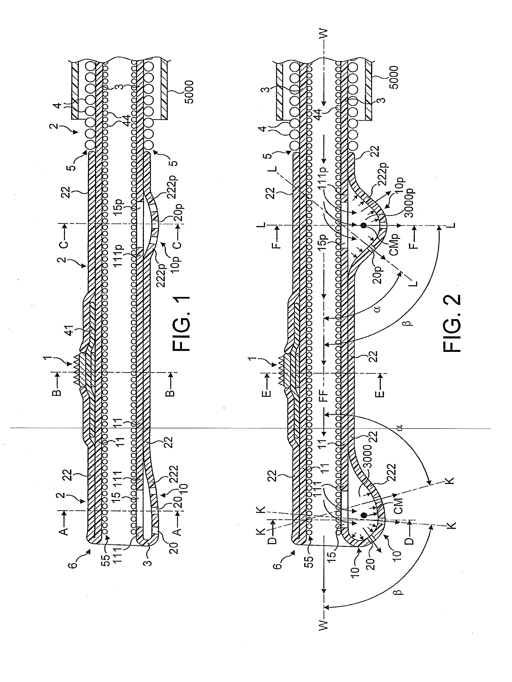
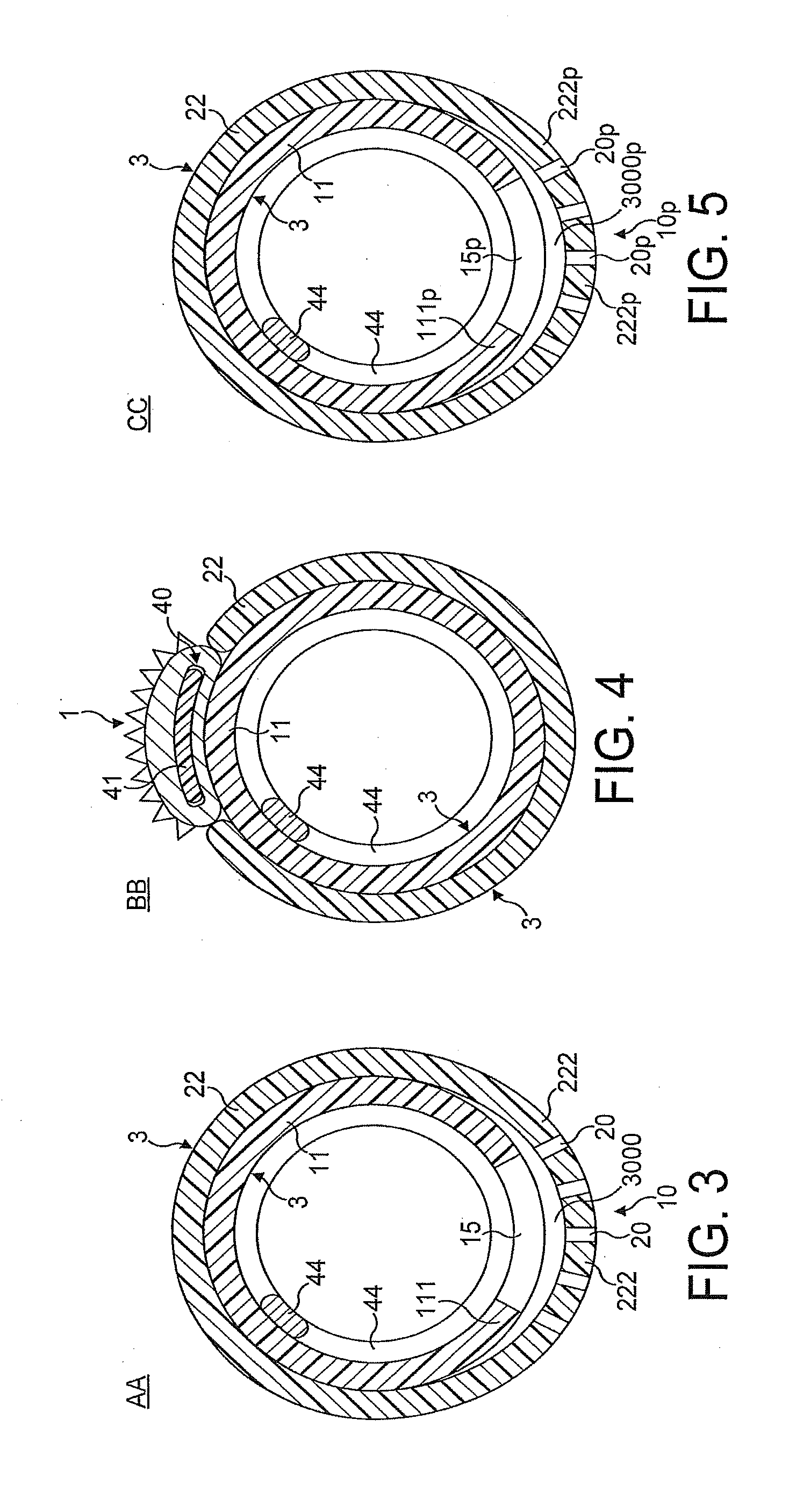
[0085]FIGS. 1 through 8 illustrate in longitudinal and transverse cross-sections a distal portion of the first most preferred embodiment of the rotational atherectomy device of the invention. The rotational atherectomy device is comprised of an abrasive element 1 which is mounted to a rotatable, flexible, hollo...


PUM


Abstract

A rotational atherectomy device for removing a stenotic tissue from a vessel of a patient is disclosed. The device comprises a rotatable, flexible, hollow drive shaft having a fluid impermeable wall defining a fluid impermeable lumen of the drive shaft and, an abrasive element mounted to a distal end portion of the drive shaft proximal to and spaced away from a distal support element formed at a distal end of the drive shaft, the distal support element being inflatable by pressurized fluid which flows in an antegrade direction through said lumen of the drive shaft and is at least partially re-directed into the distal fluid inflatable support element.

Description

CROSS-REFERENCE TO RELATED APPLICATIONS[0001]This is a continuation of U.S. application Ser. No. 12 / 373,477 filed on Jan. 12, 2009 by Dr. Leonid Shturman, which is a national phase application based on PCT / EP2007 / 056521 filed on Jun. 28, 2007, which claims priority to GB Patent Application No. 0613982.8 filed on Jul. 13, 2006, the contents of these prior applications being incorporated herein by reference.BACKGROUND[0002]1. Field[0003]The present invention relates to a rotational atherectomy device for removing or reducing stenotic lesions in blood vessels such as a human artery by rotating an abrasive element within the vessel to partially or completely ablate the unwanted material.[0004]2. Description of Related Art[0005]Atherosclerosis, the clogging of arteries, is a leading cause of coronary heart disease. Blood flow through the peripheral arteries (e.g., carotid, femoral, renal etc.), is similarly affected by the development of atherosclerotic blockages. A conventional method o...

Claims


Application Information

Patent Timeline
Patent Type & Authority Applications(United States)
IPC IPC(8): A61B17/22
CPCA61B17/320725A61B17/320758A61B2017/22067A61B2017/22068A61B2017/22071A61B2017/320766A61B2017/320008A61B2217/005A61B2217/007A61M1/0084A61B2017/320004A61M1/85
Inventor SHTURMAN, LEONID
Owner CARDIOFLOW
Why Eureka
Try Eureka