

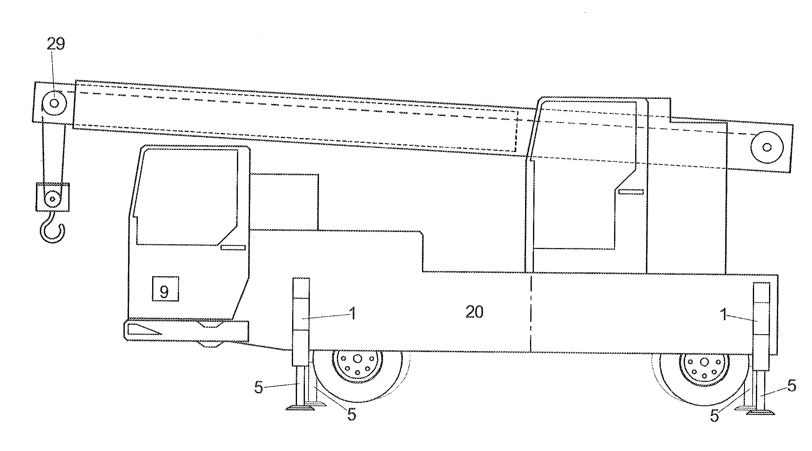
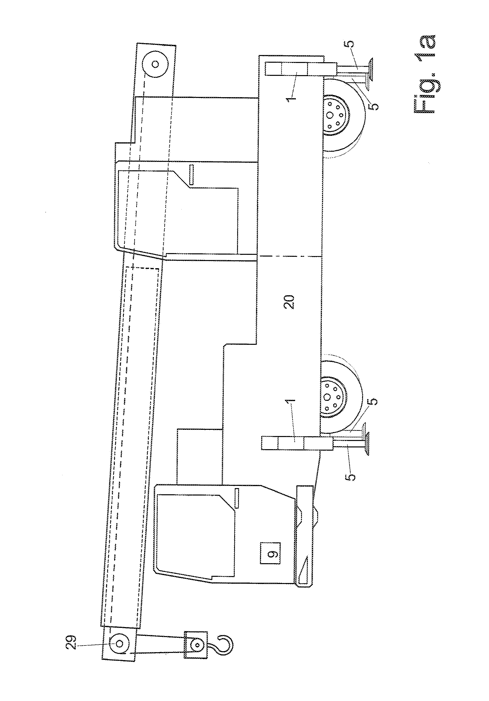
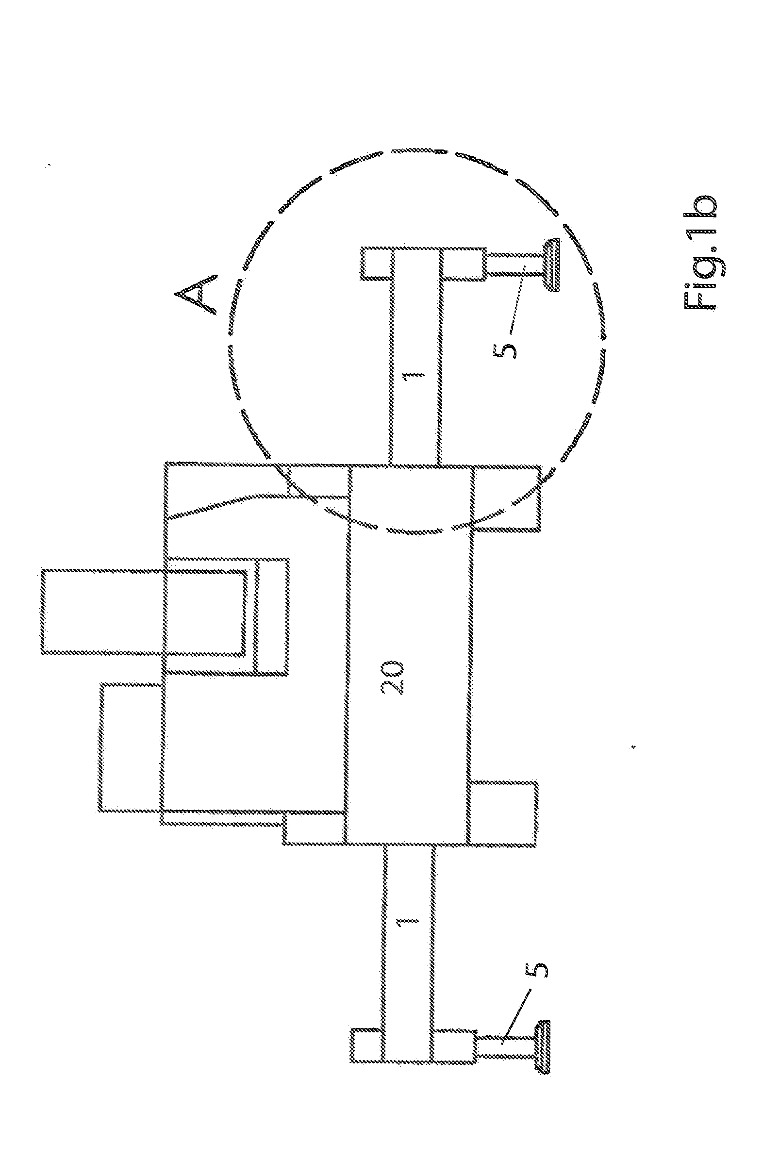
Mobile working machine
a working machine and mobile technology, applied in the field of mobile working machines, can solve problems such as the reduction of the operating parameters of the machin
- Summary
- Abstract
- Description
- Claims
- Application Information
AI Technical Summary
Benefits of technology
Problems solved by technology
Method used
Image

Examples
Embodiment Construction
[0012]Thus it is the object of the invention to provide a mobile operating machine with a support device and a method for its operation which facilitate safe operations of the operating machine.
b) Solution
[0013]This object is achieved through the features of the claims 1 and 12. Advantageous embodiments can be derived from the dependent claims.
[0014]Through the method where the control of the operating machine automatically limits the maximum permissible operating parameters of the operating machine as a function of the values reported by the sensors, it can be prevented that the operating machine is operated with parameters which lead to an instability of the operating machine and in an extreme case to the operating machine tipping over.
[0015]The limitation of the operating parameters should preferably be provided so that impermissible operating parameters at best cannot be selected at all, e.g. with respect to a possible extension length of the crane arm under a...
PUM
 Abstract
Description
Claims
Application Information