Cache Result Register for Quick Cache Information Lookup

a result register and cache technology, applied in error detection/correction, memory adressing/allocation/relocation, instruments, etc., can solve the problems of corrupt cache entries, complex address lookups, and intrusion of debugger access

Active Publication Date: 2012-07-05
NXP USA INC
View PDF6 Cites 28 Cited by
  • Summary
  • Abstract
  • Description
  • Claims
  • Application Information

AI Technical Summary

Problems solved by technology

When performing debug operations that include updating the memory window of the debugger, the process for obtaining the required information about the caches within the memory hierarchy requires complex address lookups.
If the debugger decides to bypass the complex lookup and read the cache directly, the debugger access is intrusive and can corrupt the entries within the cache.
With these conventional methods,

Method used


Image

  • Cache Result Register for Quick Cache Information Lookup
  • Cache Result Register for Quick Cache Information Lookup
  • Cache Result Register for Quick Cache Information Lookup

Examples


Embodiment Construction

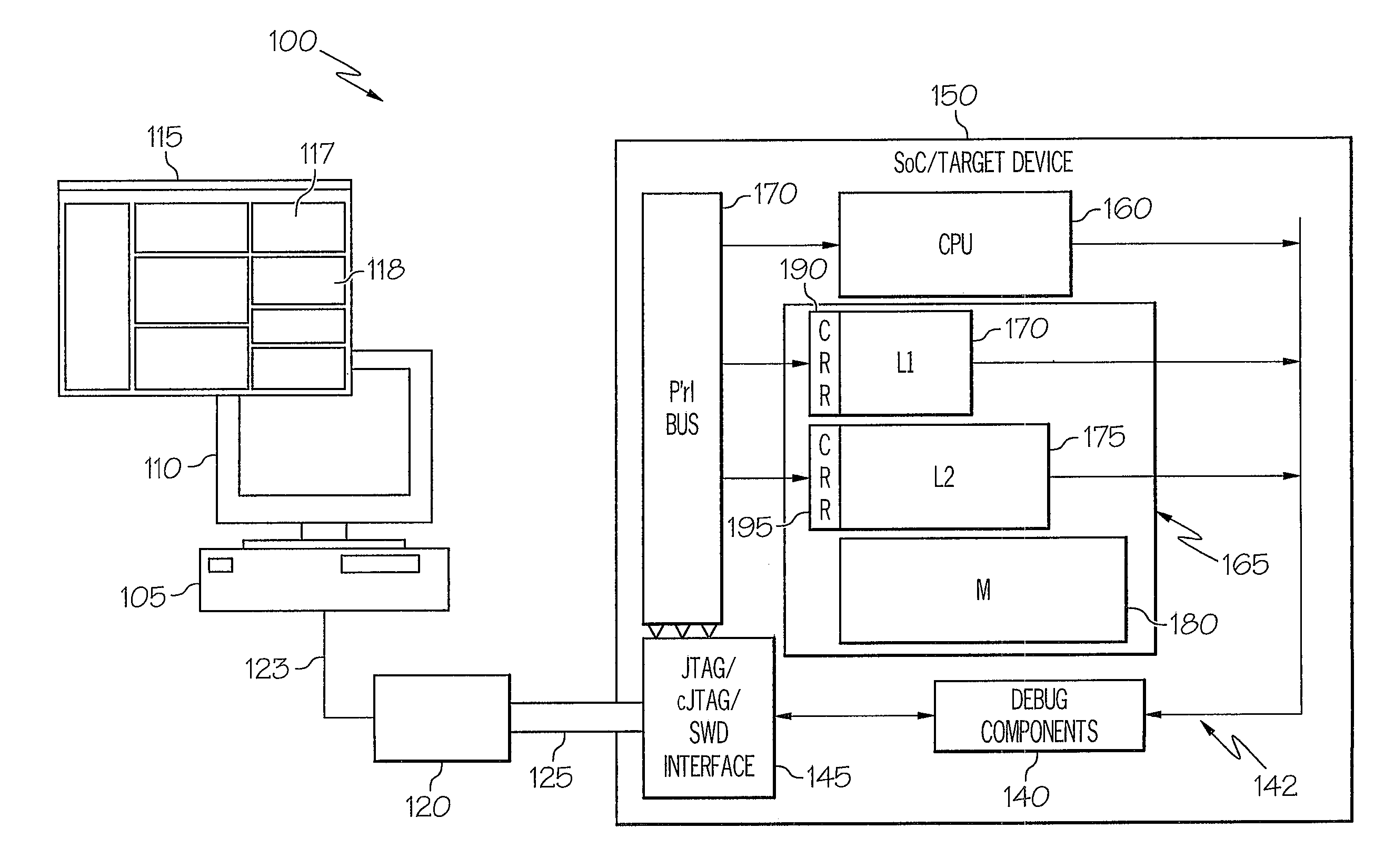
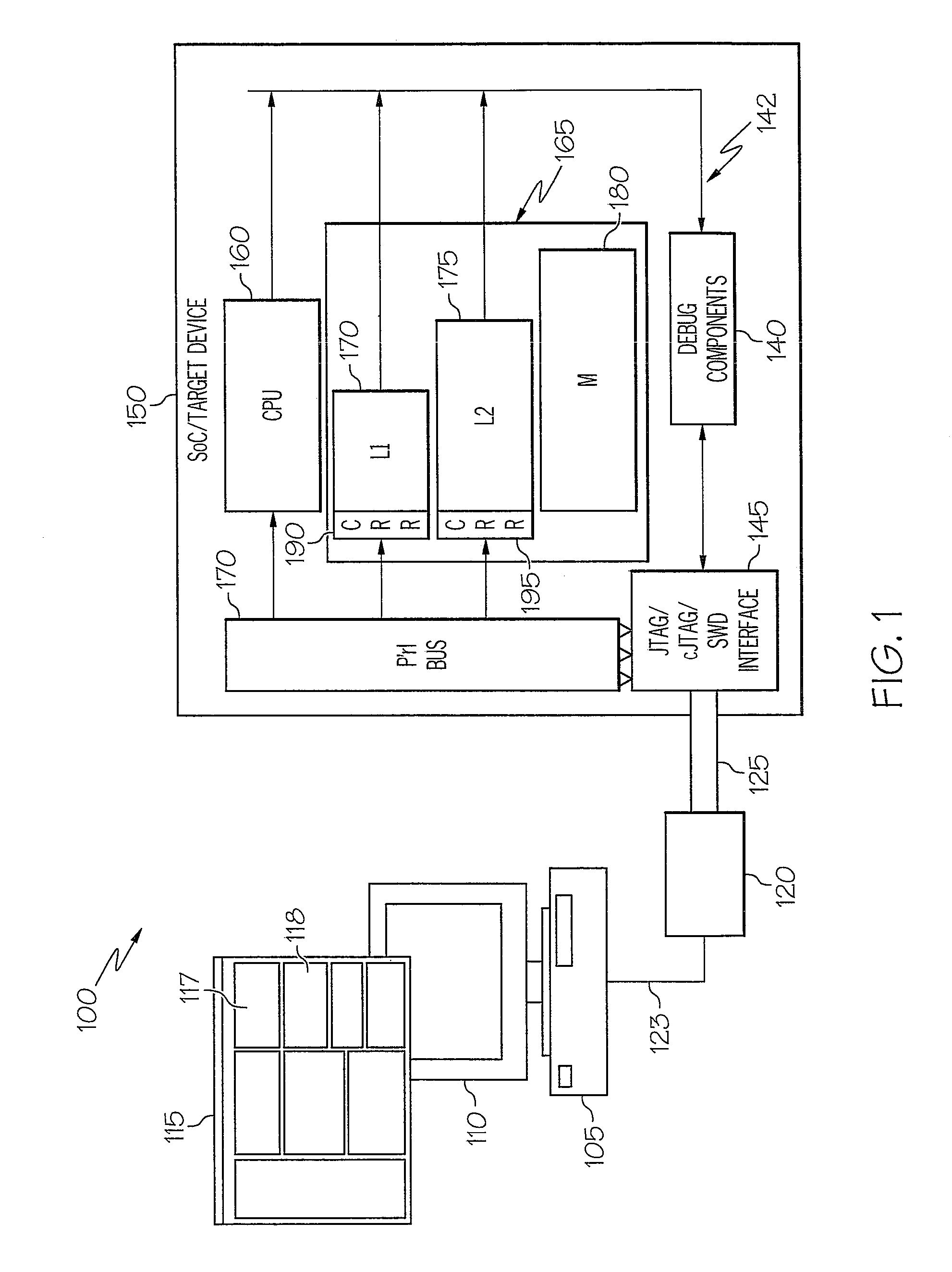
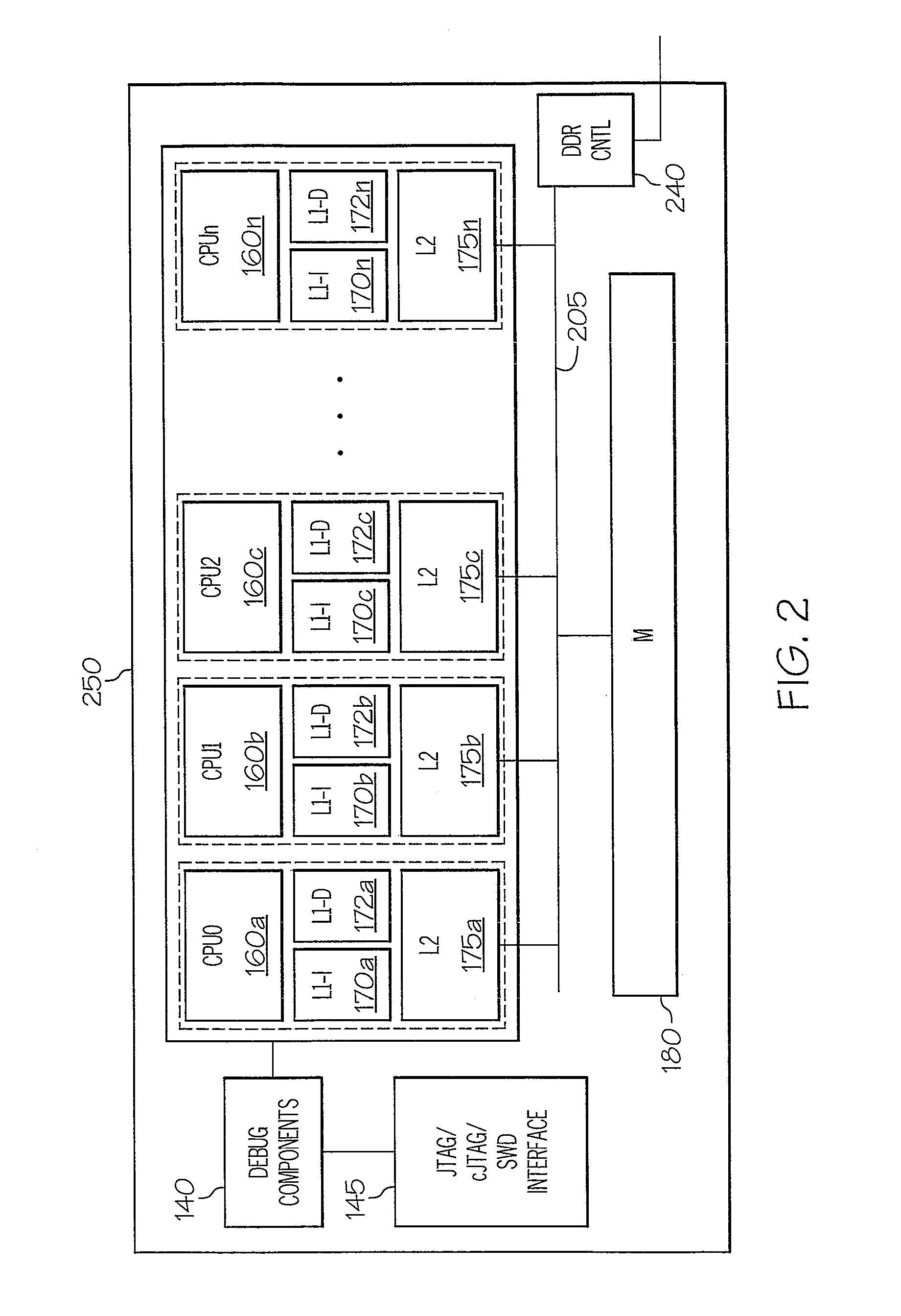
[0015]The illustrative embodiments provide a method and device that enables a software debugger executing on a data processing system connected to the (target) device to more efficiently perform debug operations involving the caches of the memory hierarchy. The device comprises: core logic (or one or more processor cores) which performs functional operations of the device; and a memory hierarchy including a memory and one or more levels of caches. Each level of cache within the memory hierarchy is configured with a cache results register (CRR). Each component at each level of the memory hierarchy is coupled to the processor core via both a system bus (for standard data operations) and via a peripheral bus (for configuration and debug operations). The device is placed in debug mode, and a debugger executing on a computer that is coupled to the device by a debug interface forwards a transaction address (TA) of interest to the debugger to the processor and request the processor complet...


PUM


Abstract

Each level of cache within a memory hierarchy of a device is configured with a cache results register (CRR). The caches are coupled to a debugger interface via a peripheral bus. The device is placed in debug mode, and a debugger forwards a transaction address (TA) of a dummy transaction to the device. On receipt of the TA, the device processor forwards the TA via the system bus to the memory hierarchy to initiate an address lookup operation within each level of cache. For each cache in which the TA hits, the cache controller (debug) logic updates the cache's CRR with Hit, Way, and Index values, identifying the physical storage location within the particular cache at which the corresponding instruction/data is stored. The debugger retrieves information about the hit/miss status, the physical storage location and/or a copy of the data via direct requests over the peripheral bus.

Description

BACKGROUND[0001]1. Technical Field[0002]The embodiments described herein generally relates to debugging systems and processes and in particular to debugging of devices having a cache-based hierarchical memory system.[0003]2. Description of the Related Art[0004]A large number of processing devices / systems that process data / instructions that are stored and / or retrieved from a memory are designed with a memory hierarchy that includes one or more levels of caches. With some of these devices / systems, the memory hierarchy is hardware coherent (i.e., coherency enforced by hardware design), while other devices / systems comprise non-coherent memory hierarchy. During conventional debugging operations involving such devices / systems where the cache(s) are not hardware coherent, the debugger has no non-intrusive, efficient way of determining which caches actually contain the cache line of data / instructions associated with the particular transaction address, and the debugger thus causes each cache...

Claims


Application Information

Patent Timeline
IPC IPC(8): G06F12/08
CPCG06F11/362G06F12/0897
Inventor EHRLICH, ROBERTHEUER, KEVIN C.MCGOWAN, ROBERT A.
Owner NXP USA INC
Why Eureka
Try Eureka