
Locking Panel Veneer System

Active Publication Date: 2012-07-12
MANN MATTHEW
View PDF14 Cites 5 Cited by
  • Summary
  • Abstract
  • Description
  • Claims
  • Application Information

AI Technical Summary

Benefits of technology

[0016]Ideally, the suspension rail has some flexibility incorporated into its structure or is comprised of a material that allows for flexing or bending or one or bothe of the mounting bars. Such functionality can include structure in the form of a c-shaped groove along the length of the suspension rail to which the mounting bar is in communication with. The c-shaped channel allows for the mounting bar to be flexed toward or away from the body of the suspension rail to allow for ease of insertion of the mounting bar into a facade system on installation.
[0022]Included in embodiments of the invention are veneer systems comprising at least two universal brackets for providing support against pullout of the panels. Each universal bracket (otherwise referred to as a suspension rail) can provide a surface for engaging another panel or for engaging with a corresponding bracket of another panel. Preferably, each bracket comprises an engagement surface substantially along the length of one side of the panel, or a major part of the length thereof, such as 50% or more. The brackets can also be configured to be a single piece providing one or more, typically two, additional engagement surfaces. Preferably, the bracket(s) are embedded in the panels during the manufacturing process or prior to installation to provide easy to install panels. The brackets, together with the length of the engagement surfaces provided by the panels themselves, can provide a total engaging length of 50% or more of the perimeter of the panel and up to 150% of the perimeter, or any engagement length between. Preferably, panels of the system with integral bracket(s) engage 100% to 150% of perimeter length.

Problems solved by technology

Conventional mortar-based facade systems, including brick and stone are as difficult to remove as they are to install.
This limits installation, especially in areas where seasonal changes occur, to relatively dry and ambient conditions.
Another disadvantage to conventional stone and brick facade systems is that such systems are labor intensive, messy, and time consuming to install.
Dry rot of the wall itself due to a lack of ventilation is a common problem for such systems.
Further, if moisture seeps in behind the brick or stone veneer, mold, mildew, and deterioration of the wall can develop increasing the chance of failure of the veneer.
Buildings are known to settle for some time after construction, leading to movement of walls.
Typical mortar-based systems do not allow or provide for very little allowance for such seismic movement.
Often times a mortar-based veneer will crack in response to environmental changes and generally over time.
Cracking allows for moisture to seep into the system and provides an opportunity for loosening of the stones or brick, which generally requires replacement of the mortal to salvage the veneer, and which in turn is typically an expensive endeavor.
Existing mortarless systems, however, do not have the advantage of strength to resist pullout of the modular panels.

Method used


Image

  • Locking Panel Veneer System
  • Locking Panel Veneer System
  • Locking Panel Veneer System

Examples


Embodiment Construction

[0034]Reference will now be made in detail to various exemplary embodiments of the invention. The following detailed description is presented for the purpose of describing certain embodiments in detail and is, thus, not to be considered as limiting the invention to the embodiments described. More particularly, specific embodiments of the invention are described in reference to the drawings, however, it will be noted that the embodiments provided do not need to contain all elements described and can be combined with individual features of other embodiments described in this specification.

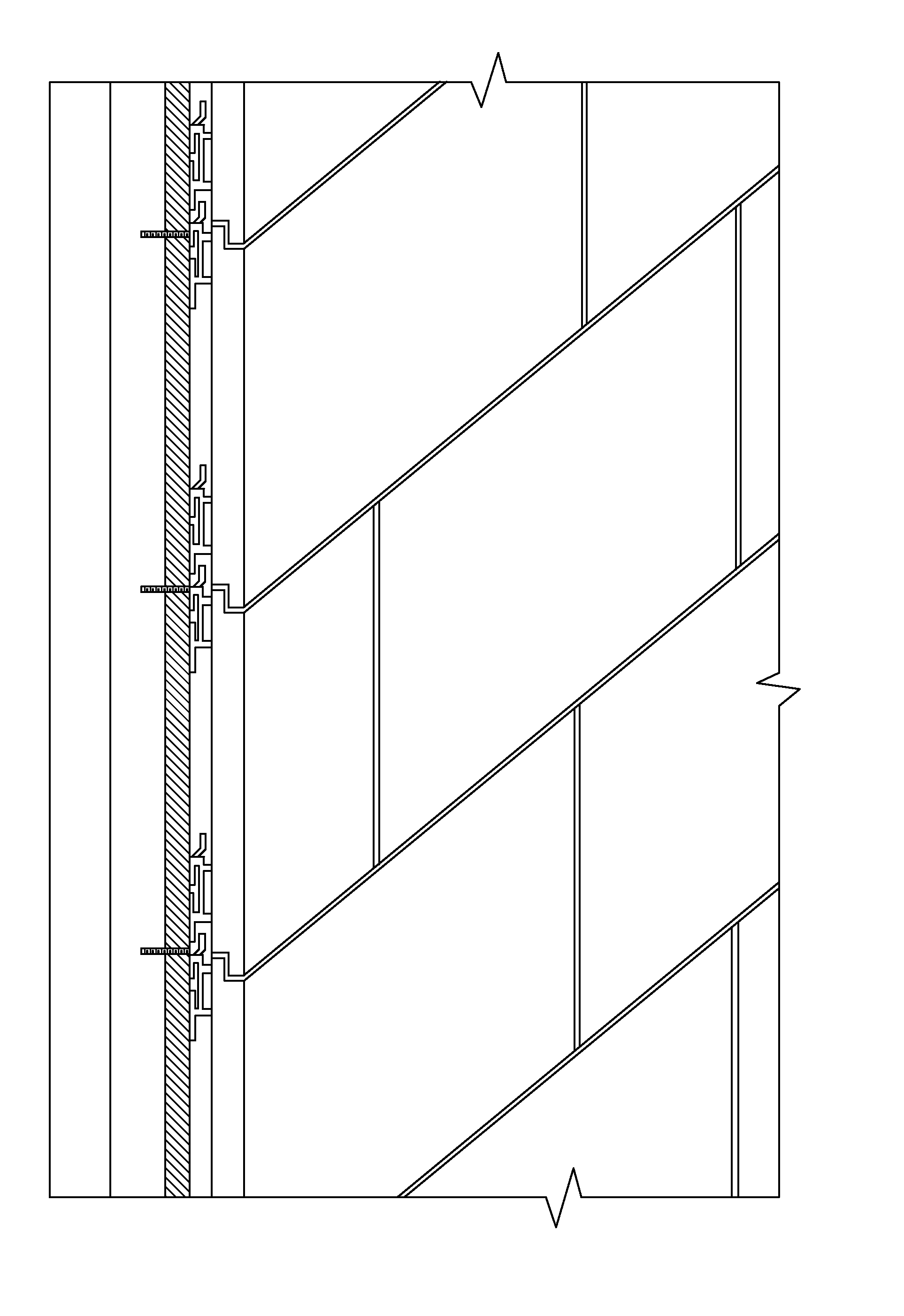
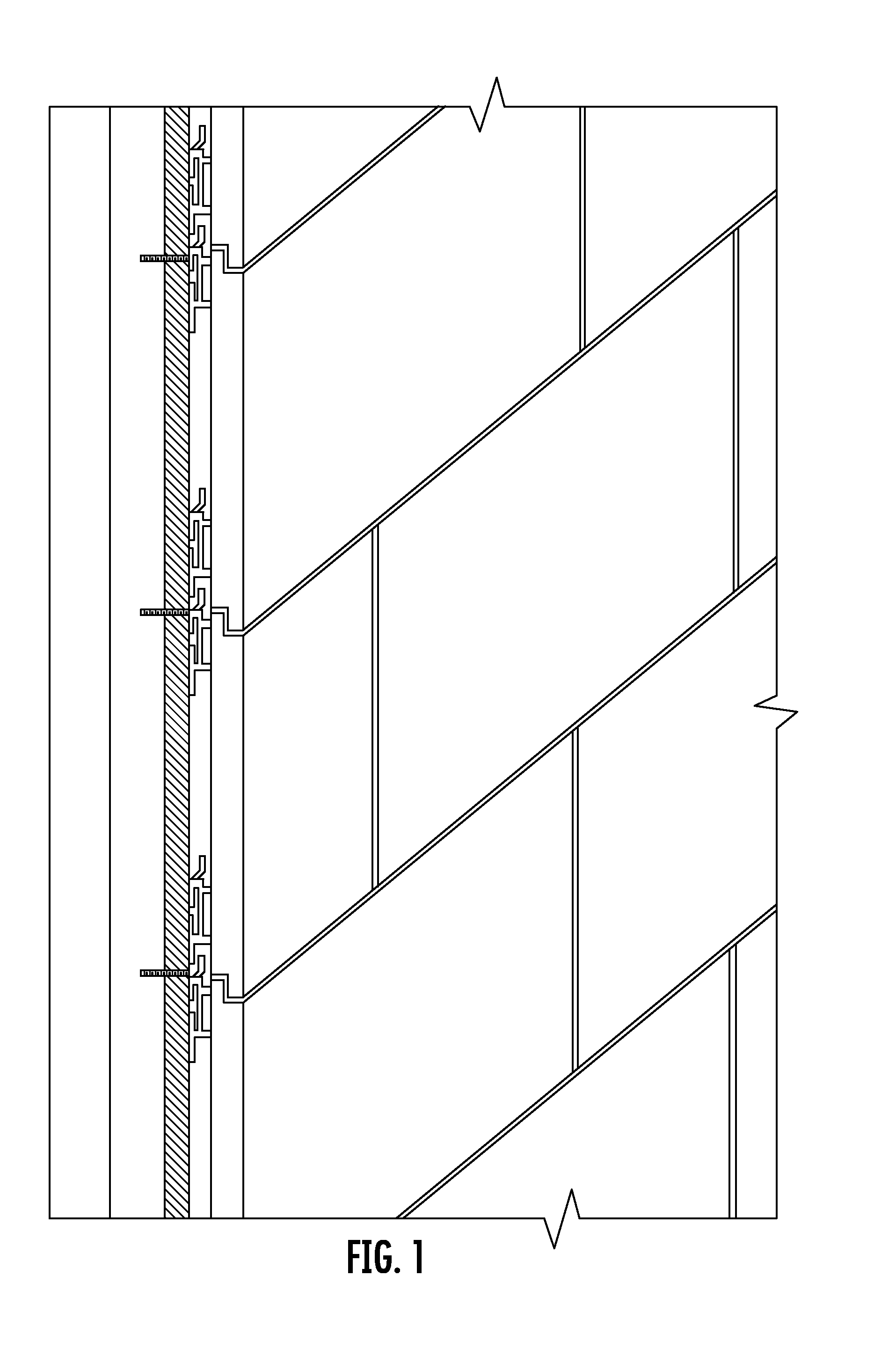
[0035]FIG. 1 provides a schematic diagram showing installation of a veneer system according to the invention. This system, and any system or panel described in this specification, can be installed with or without mortar. One advantage of the systems of the invention is that mortar is not required, but can be optional for additional support, strength, or longevity of the overall system. As shown in FI...


PUM


Abstract

The present invention relates to the field of mortarless, stone-like veneer systems for walls. More specifically, the present invention relates to facade systems comprising a plurality of panels with surfaces for engaging other panels in the system and for resisting pullout of a panel once installed. Further provided are facade systems comprising a plurality of panels which provide stacked-stone corners for walls, columns, and posts when installed. Preferred are systems comprising modular facade panels having (i) a front face for forming part of a first facade, wherein the face is formed as a plurality of stacked stones and has a concave rectilinear polygonal outline configured for mating with adjacent panels when installed in a facade system; (ii) a back side with a suspension rail in communication therewith; and (iii) left and right sides for forming part of another facade in an intersecting plane. Such panel systems provide a seamless veneer with a strength nearing that of mortar-based systems but having the ease of installation provided by modular mortarless systems.

Description

CROSS-REFERENCE TO RELATED APPLICATIONS[0001]This application claims priority to and the benefit of the filing date of U.S. Provisional Patent Application Nos. 61 / 362,740 and 61 / 486,850 filed respectively on Jul. 9, 2010 and May 17, 2011, the disclosures of each of which are hereby incorporated by reference herein in their entireties.BACKGROUND OF THE INVENTION[0002]1. Field of the Invention[0003]The present invention relates to the field of mortarless, stone-like veneer systems for walls. More specifically, the present invention relates to facade systems comprising a plurality of panels with surfaces for engaging other panels in the system and for resisting pullout of a panel once installed. Further provided are facade systems comprising a plurality of panels which provide stacked-stone corners for walls, columns, and posts when installed. Such panel systems provide a seamless veneer with a strength nearing that of mortar-based systems but having the ease of installation provided b...

Claims


Application Information

Patent Timeline
IPC IPC(8): E04B2/08E04C3/00
CPCE04F13/0873E04F13/0805E04F13/0816E04F2203/065E04C2003/0473E04F2203/02E04C2003/0434E04F13/0733
Inventor MANN, MATTHEW
Owner MANN MATTHEW
Learn More