Star Wheel Conveyor Outfeed Mechanism and Method

a conveyor and star wheel technology, applied in the direction of mechanical conveyors, conveyor parts, packaging, etc., can solve the problems of unpredictable container handling and possible damage, and reducing the efficiency of inspection machines

Inactive Publication Date: 2012-07-12
EMHART GLASS SA
View PDF2 Cites 18 Cited by
  • Summary
  • Abstract
  • Description
  • Claims
  • Application Information

AI Technical Summary

Benefits of technology

[0018]The apparatus of the present disclosure is of a construction which is both durable and long lasting, and which will require little or no maintenance to be provided by the user throughout its operating lifetime. The apparatus of the present disclosure is also of inexpensive construction to enhance its market appeal and to thereby afford it the broadest possible market. Finally, all of the aforesaid advantages and objectives are achieved without incurring any substantial relative disadvantage.

Problems solved by technology

However, for larger bottles, a 9 or 6 pocket star wheel conveyor is typically used in the controller of the servo motor drive of the star wheel conveyor does not provide for a dwell that will allow the outfeed stripper and outfeed wheel to discharge a container.
In such conditions, the outfeed of the bottle is governed by the star wheel conveyor forcing the container against the outfeed stripper and the outfeed wheel which is running it a tangential speed matching the linear conveyor speed and since the star wheel conveyor tangential speed is much greater the additive velocity imported to the container by the tangential speed of the star wheel conveyor and the rotational speed of the outfeed wheel results in unpredictable container handling and possible damage.
Such compromised operational speed reduction reduces the efficiency of the inspection machine which typically operates in the range of 200-400 containers per minute.
It is also known to provide in various mechanical guides in the outfeed area of the inspection machine in an attempt to stabilize container discharge over such mechanical devices at costs and setup time which further reduces the efficiency of the inspection machine.

Method used


Image

  • Star Wheel Conveyor Outfeed Mechanism and Method
  • Star Wheel Conveyor Outfeed Mechanism and Method
  • Star Wheel Conveyor Outfeed Mechanism and Method

Examples


Embodiment Construction

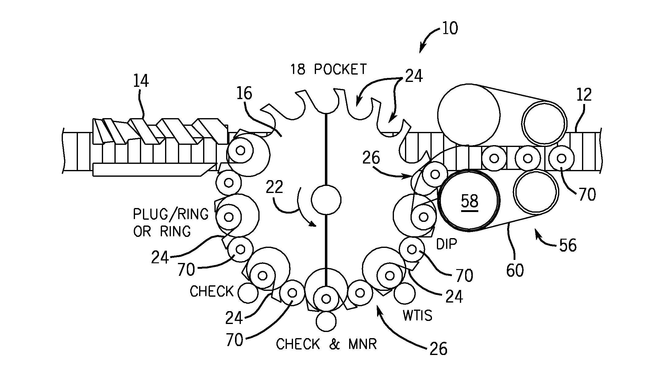
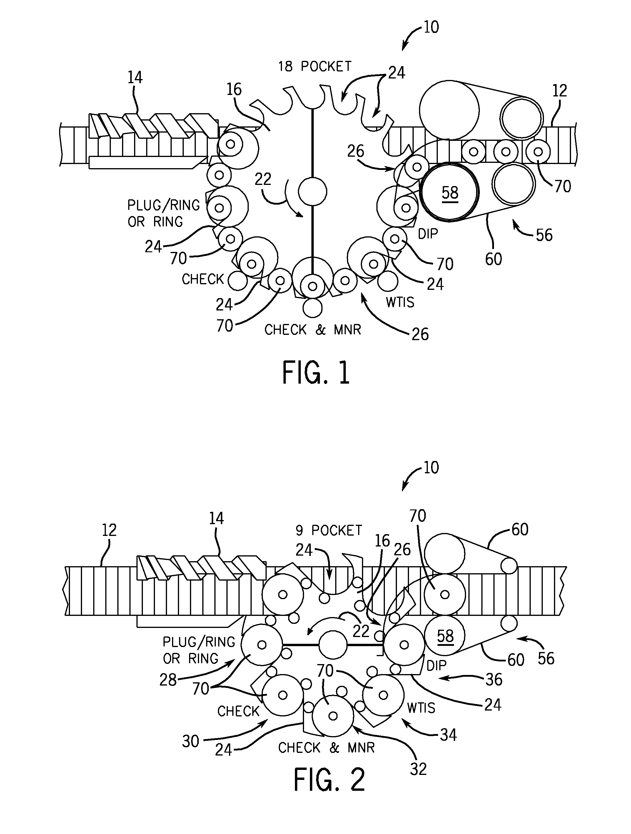
[0030]As part of a process of manufacturing containers, particularly glass containers, it is necessary to inspect the containers after they are molded to insure specific quality requirements for the containers. An inspection machine 10 typically provides inspection stations at which inspections of the glass container are performed on various portions of the container. One such inspection machine 10 includes what is referred to as a star wheel 16 which receives containers from a linear conveyor 12 rotates the containers with stops, also referred to as dwells, at which point an inspection takes place. As the circular star wheel 16 rotates about a rotational path 22, it stops or dwells at specific inspection points. Upon completion of all of the inspections, the container is off-loaded at a non-inspection position to transfer the container 70 back to the linear conveyor 12.

[0031]The size and configuration of the star wheel 16 depends on the type of bottle that is being moved through an...


PUM


Abstract

A method and apparatus for inspection of containers including a circular star wheel conveyor having a plurality of intermediate annular inspection pockets and at least one non-inspection position. The method includes the steps of providing an outfeed stripper configured to engage a container disposed in the non-inspection position aligning the outfeed stripper inside the circumference of the star wheel conveyor and aligning the outfeed stripper with the conveyor and with the rotational path of the star wheel. Positioning an outfeed mechanism adjacent to the star wheel conveyor and operating the outfeed mechanism at a desired conveyor speed. Controlling the movement of the star wheel conveyor to align the container with the outfeed stripper and the outfeed mechanism only at the non-inspection position regardless of the number of angular inspection positions.

Description

BACKGROUND OF THE INVENTION[0001]The present invention relates to container inspection machines and more particularly to a method and apparatus of controlling a transfer of a container from a circular star wheel conveyor of a container inspection apparatus onto a conveyor with a transfer apparatus.[0002]The container inspection machine typically includes a conveyor that is configured to transport containers including inspection machine and a star wheel conveyor which accepts containers from the conveyor, inspects the container at various inspection positions and then discharges the container from the star wheel onto the conveyor for further handling and processing. The conveyor typically is linear and includes a screw transport which spaces containers on the conveyor and aligns the container with a pocket defined in the star wheel conveyor. In a typical star wheel conveyor configuration, the star wheel conveyor defines a plurality of intermediate angular positions and is configured ...

Claims


Application Information

Patent Timeline
Patent Type & Authority Applications(United States)
IPC IPC(8): B65G47/84
CPCB65G47/846B65G2207/08B65G2201/0244
Inventor BRIGGS, SCOTT M.GIOMETTI, STEPHEN MATTHEWSHAY, TIMOTHY W.
Owner EMHART GLASS SA
Why Eureka
Try Eureka