Oscillator circuit

Active Publication Date: 2012-07-12
MITSUMI ELECTRIC CO LTD
View PDF3 Cites 5 Cited by
  • Summary
  • Abstract
  • Description
  • Claims
  • Application Information

AI Technical Summary

Benefits of technology

[0015]In one aspect, the present disclosure provides an oscillator circuit which has a simple composi

Problems solved by technology

In the related art oscillator circuit of FIG. 5, the oscillating frequency of the built-in oscillator 1 is constant even when the main clock signal is in a low-speed operation mode, so that it is difficult to reduce power dissipation of the related art oscillator circuit.
Further, the related art osc

Method used


Image

  • Oscillator circuit
  • Oscillator circuit
  • Oscillator circuit

Examples


Example

[0024]A description will be given of embodiments of the present disclosure with reference to the accompanying drawings.

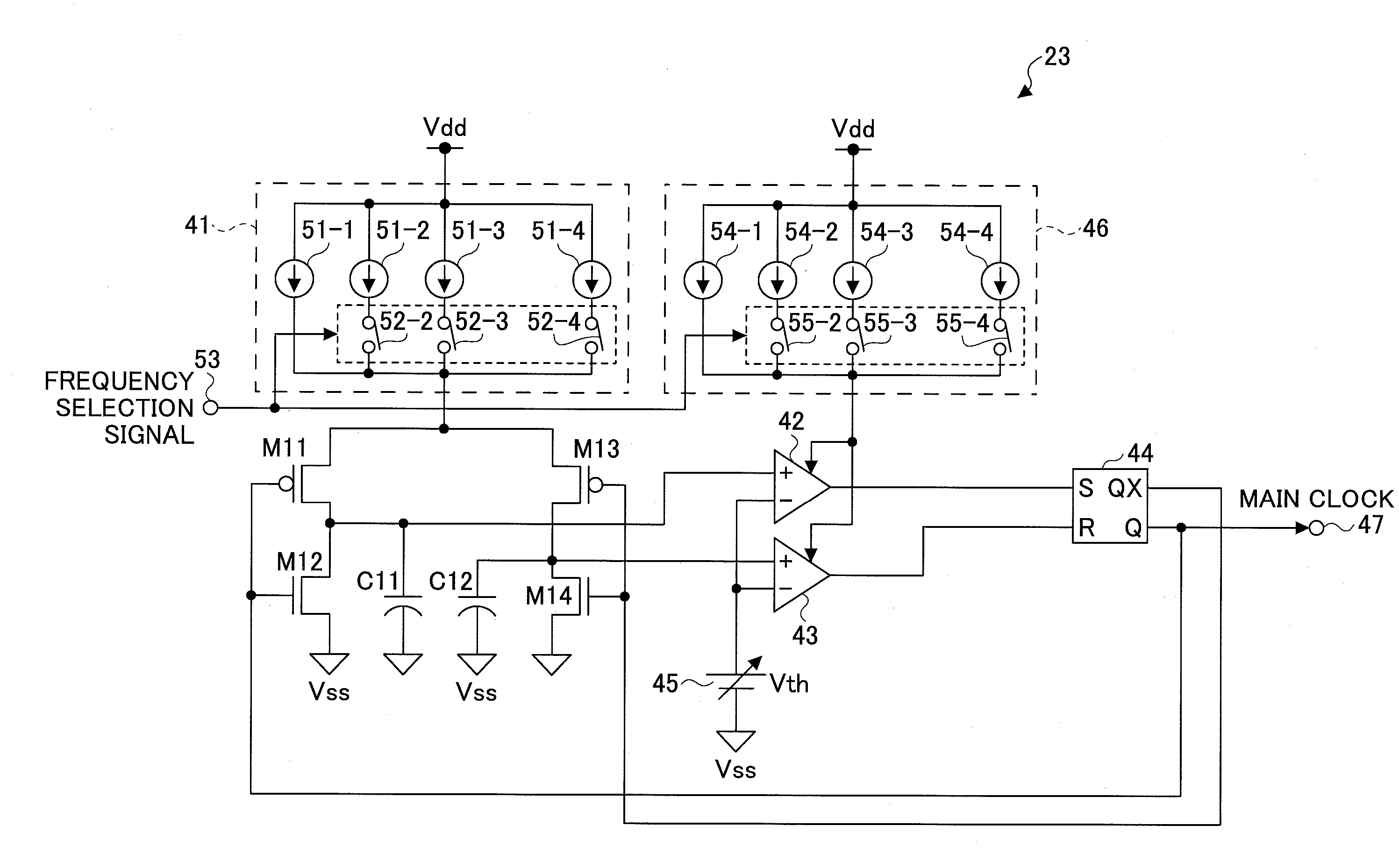
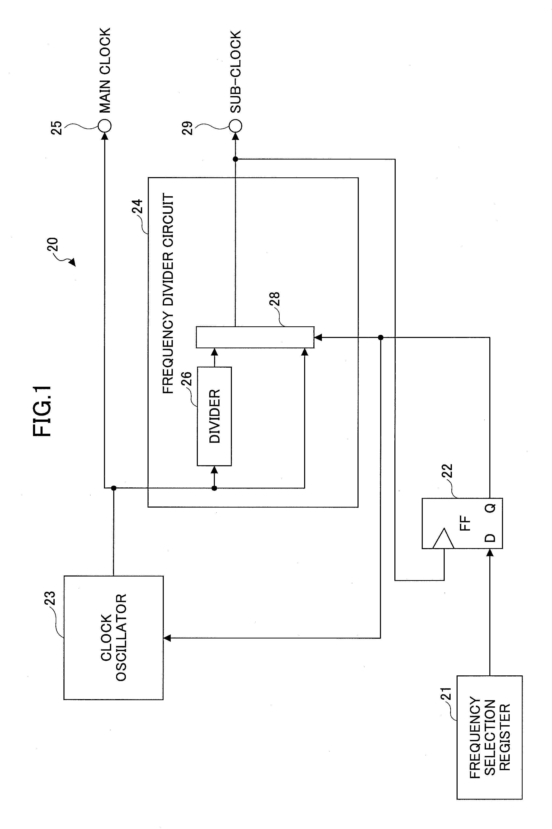
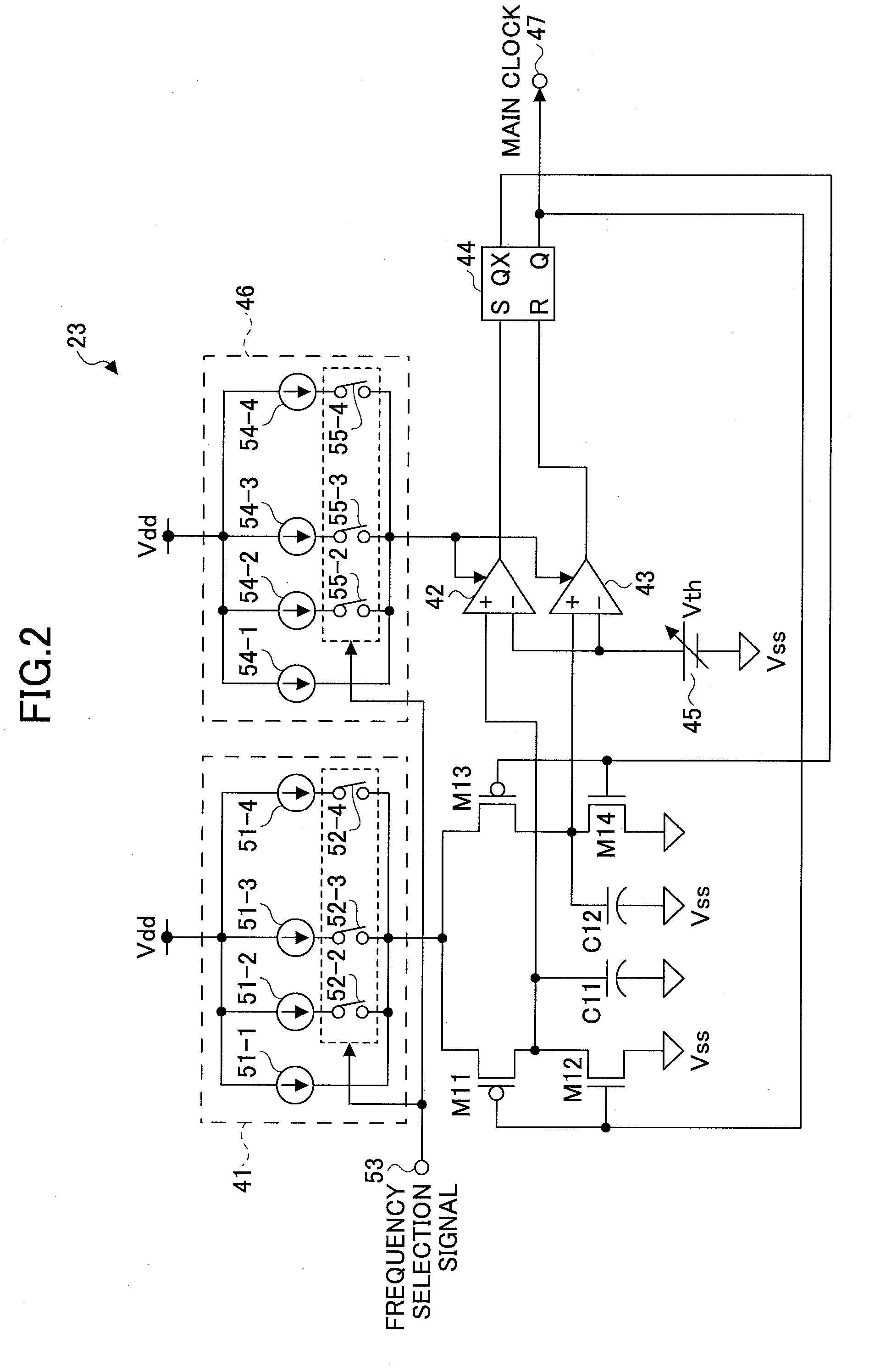
[0025]FIG. 1 is a block diagram showing the composition of an oscillator circuit 20 of an embodiment of the present disclosure. This oscillator circuit 20 is formed as a semiconductor integrated circuit.

[0026]In the oscillator circuit 20 of FIG. 1, a frequency selection signal is stored in a frequency selection register 21. The frequency selection signal is output from a CPU (which is not illustrated) and indicates the value 1 or the value 0. The frequency selection signal output from the frequency selection register 21 is supplied to a flip-flop 22. The frequency selection signal is synchronized with a sub-clock signal and stored in the flip-flop 22. The frequency selection signal output from the flip-flop 22 is supplied to a clock oscillator 23, and, at the same time, supplied to a selector 28 provided in a frequency divider circuit 24.

[0027]For example, the clock...


PUM


Abstract

An oscillator circuit includes a clock oscillator which outputs a main clock signal having an oscillating frequency switched between a high frequency and a low frequency in response to a frequency selection signal, and a frequency divider circuit which outputs a sub-clock signal having a divided frequency equivalent to a frequency division ratio of the oscillating frequency of the main clock signal, the frequency division ratio being switched in response to the frequency selection signal. The divided frequency of the sub-clock signal is predetermined for each of the high frequency and the low frequency to which the oscillating frequency is switched in response to the frequency selection signal.

Description

CROSS-REFERENCE TO RELATED APPLICATION[0001]This application is based upon and claims the benefit of priority of Japanese patent application No. 2011-004052, filed on Jan. 12, 2011, the entire contents of which are incorporated by reference in their entirety.BACKGROUND OF THE INVENTION[0002]1. Field of the Invention[0003]The present disclosure relates to an oscillator circuit.[0004]2. Description of the Related Art[0005]FIG. 5 shows the circuit composition of an oscillator circuit according to the related art. As shown in FIG. 5, in this oscillator circuit, a built-in oscillator 1 generates a clock signal with a frequency on the order of several hundreds of 1 MHz (megahertz). This clock signal is supplied to a frequency divider circuit 2. The frequency divider circuit 2 converts the clock signal into a ½ frequency signal, a ¼ frequency signal, a ⅛ frequency signal, and a 1 / 16 frequency signal, and supplies each divided frequency signal to a frequency selection circuit 3. The frequen...

Claims


Application Information

Patent Timeline
IPC IPC(8): H03L7/00H03K3/02H03K3/354H03K5/08
CPCH03K4/501G06F1/04H03K5/13
Inventor ABE, MAKIOINOUE, FUMIHIROKIMURA, JUNICHI
Owner MITSUMI ELECTRIC CO LTD
Why Eureka
Try Eureka