

Shaped Reflectors for Enhanced Optical Diffusion in Backlight Assemblies
a backlight and reflector technology, applied in the field of backlight optical diffusers, can solve the problems of reducing the optical transmission of the diffuser, increasing the overall thickness of the lcd, and reducing the transmission of light, so as to achieve enhanced light homogenization, enhanced diffuser enhancement, and optimized trade
- Summary
- Abstract
- Description
- Claims
- Application Information
AI Technical Summary
Benefits of technology
Problems solved by technology
Method used
Image

Examples
Embodiment Construction
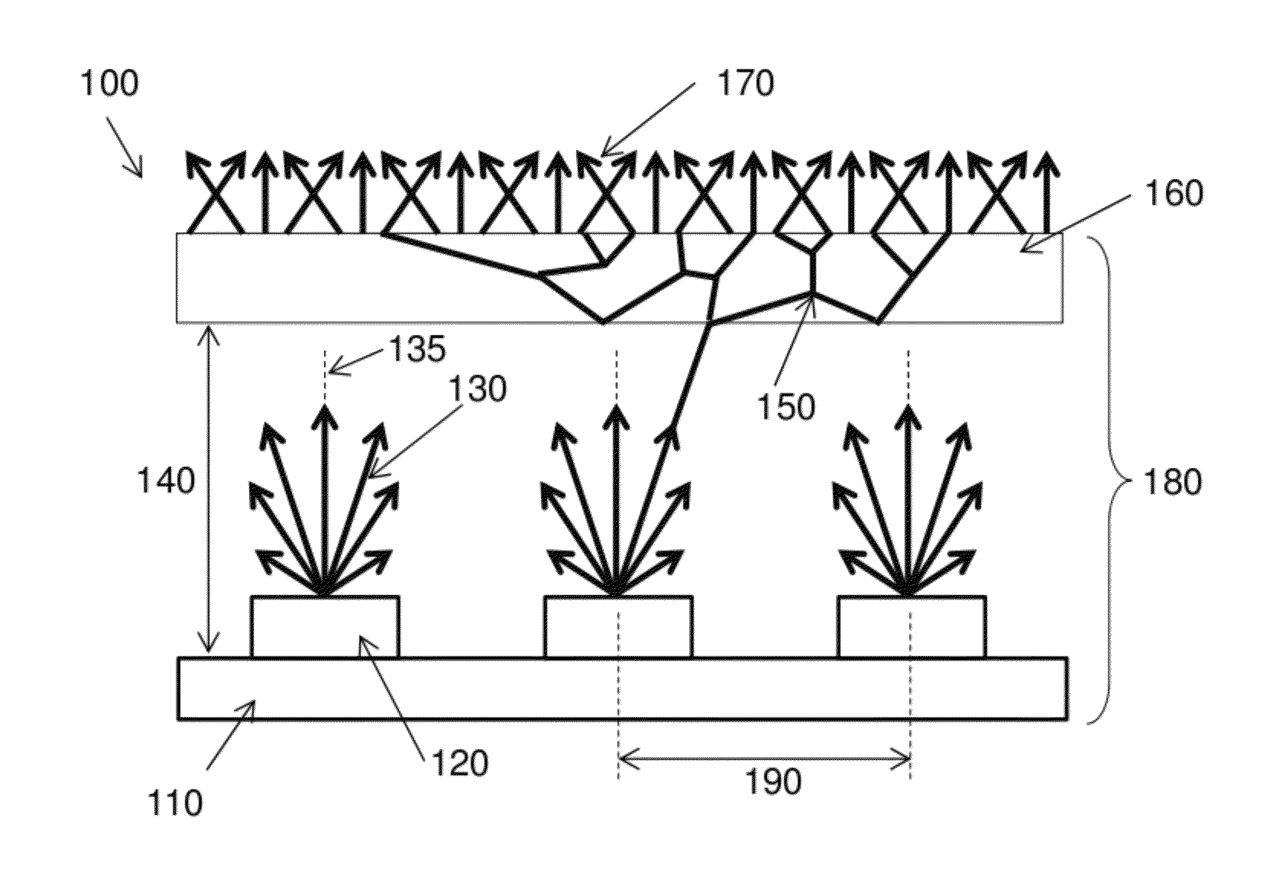
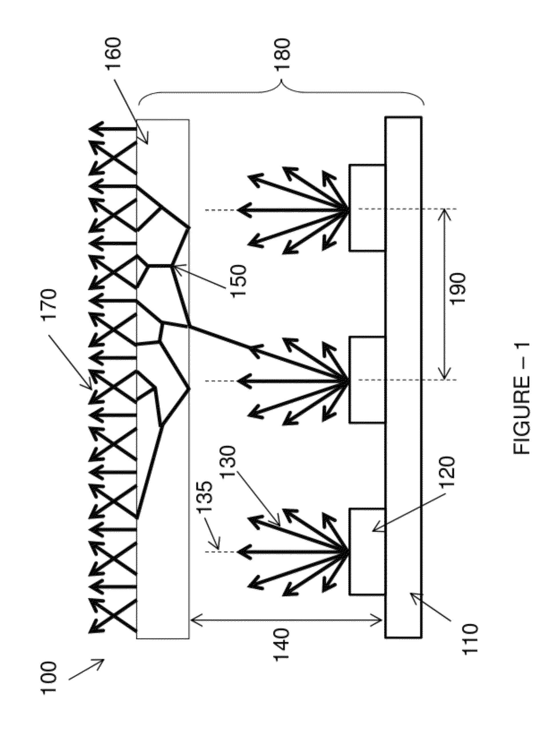
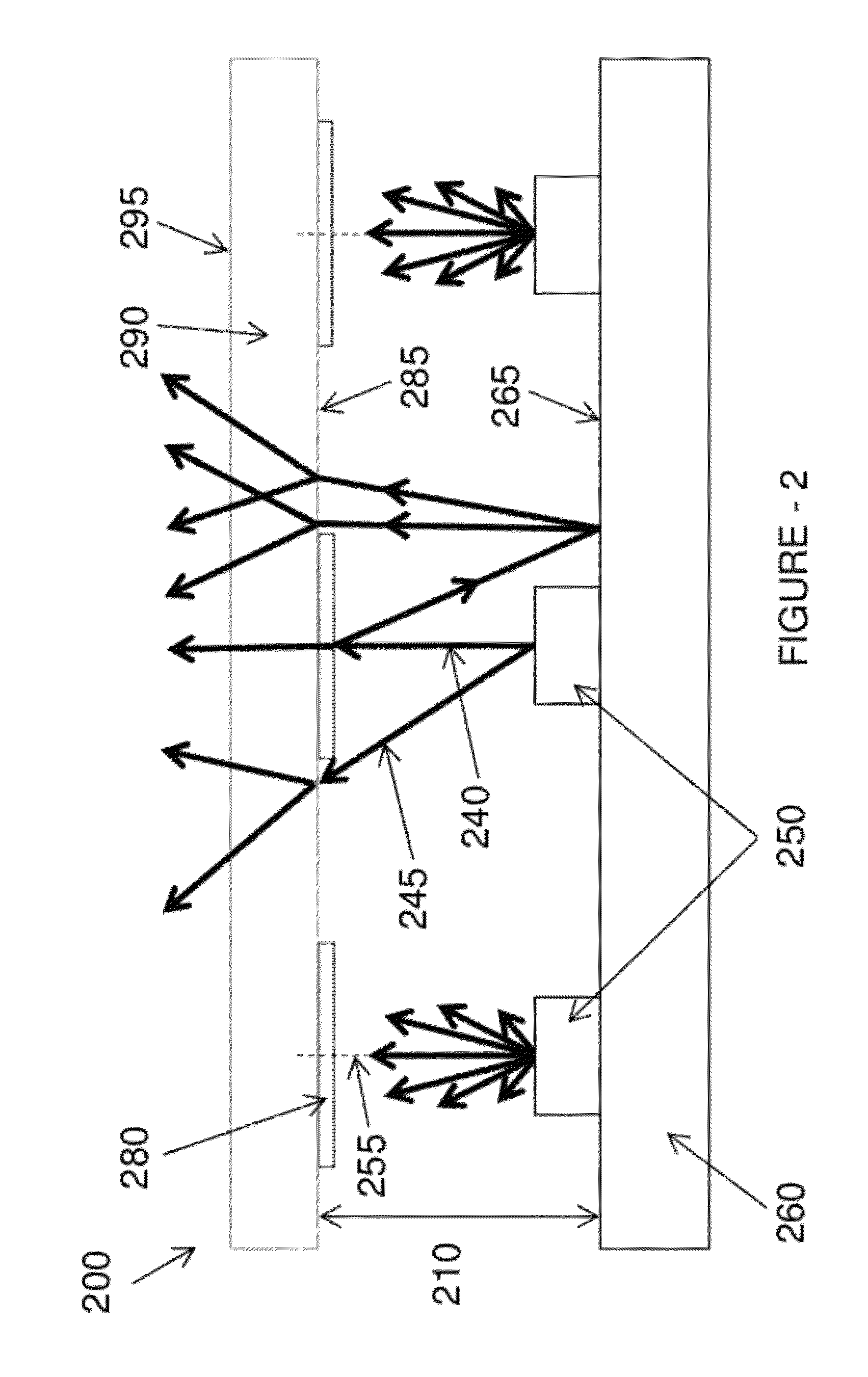
[0007]Exemplary embodiments provide a diffusing element such as a sheet of plastic or glass that serves to suspend a plurality of shaped reflectors directly above each LED in a planar 2-D array. In doing so the strongest on-axis light from each LED is predominately reflected back toward the LED where, via multiple reflections, the light homogenization is enhanced. In general, it may be preferable that the reflectors are not 100% reflective but instead are partially reflective in order to allow a certain amount of the on-axis light to pass directly through, with the particular amount being optimized for the application. This serves to avoid an ‘eclipse’ or ‘shadow’ effect that may otherwise result from a reflectivity of 100% that could be counter-productive to the goal of uniformly homogenizing the light. A large degree of flexibility exists in selecting the materials, shapes, and fabrication techniques of the reflectors, and this allows for optimized trades considering performance a...
PUM
 Abstract
Description
Claims
Application Information