Radio system and radio communication method

a radio communication and radio system technology, applied in the field of radio system and radio communication method, can solve the problems of deteriorating signal to interference power ratio, difficult to prevent cell interference, low rate of backhaul connection between relay base station and donor base station, etc., and achieve the effect of reducing transmission power

Inactive Publication Date: 2012-07-12
HITACHI LTD
View PDF4 Cites 37 Cited by
  • Summary
  • Abstract
  • Description
  • Claims
  • Application Information

AI Technical Summary

Benefits of technology

[0079]Further, since the mobile station communicates with the relay (femto) base station, the battery ...

Problems solved by technology

This leads to such a problem that it would be difficult to prevent the interference between the cells.
The interference between the cells means that a ratio of a signal to interference power is deteriorated by overlapping of signals from the neighborhood base stations on a frequen...

Method used


Image

  • Radio system and radio communication method
  • Radio system and radio communication method
  • Radio system and radio communication method

Examples


Embodiment Construction

1. System

[0089]FIG. 3 illustrating a configuration diagram of a relay radio system according to an embodiment.

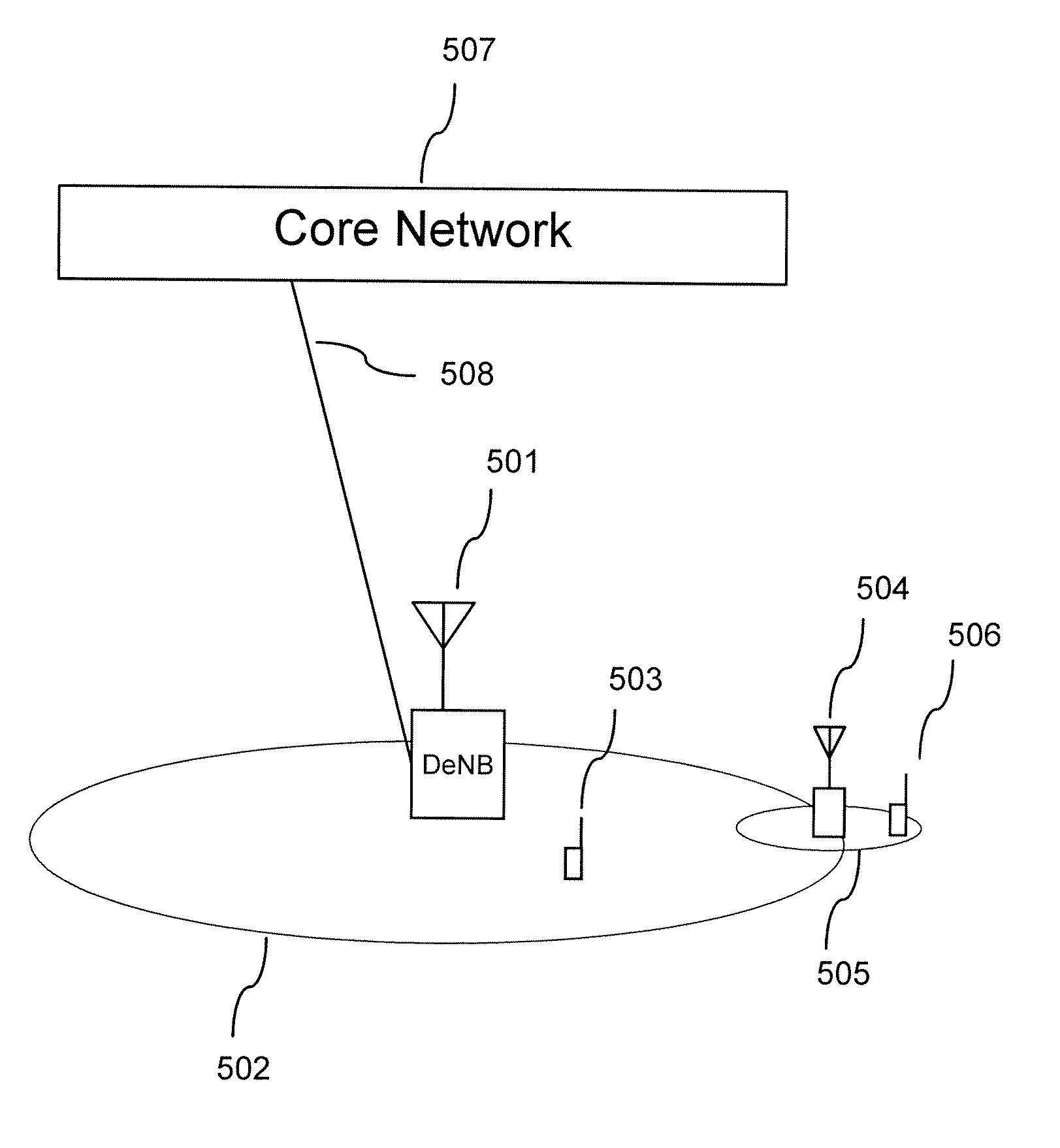
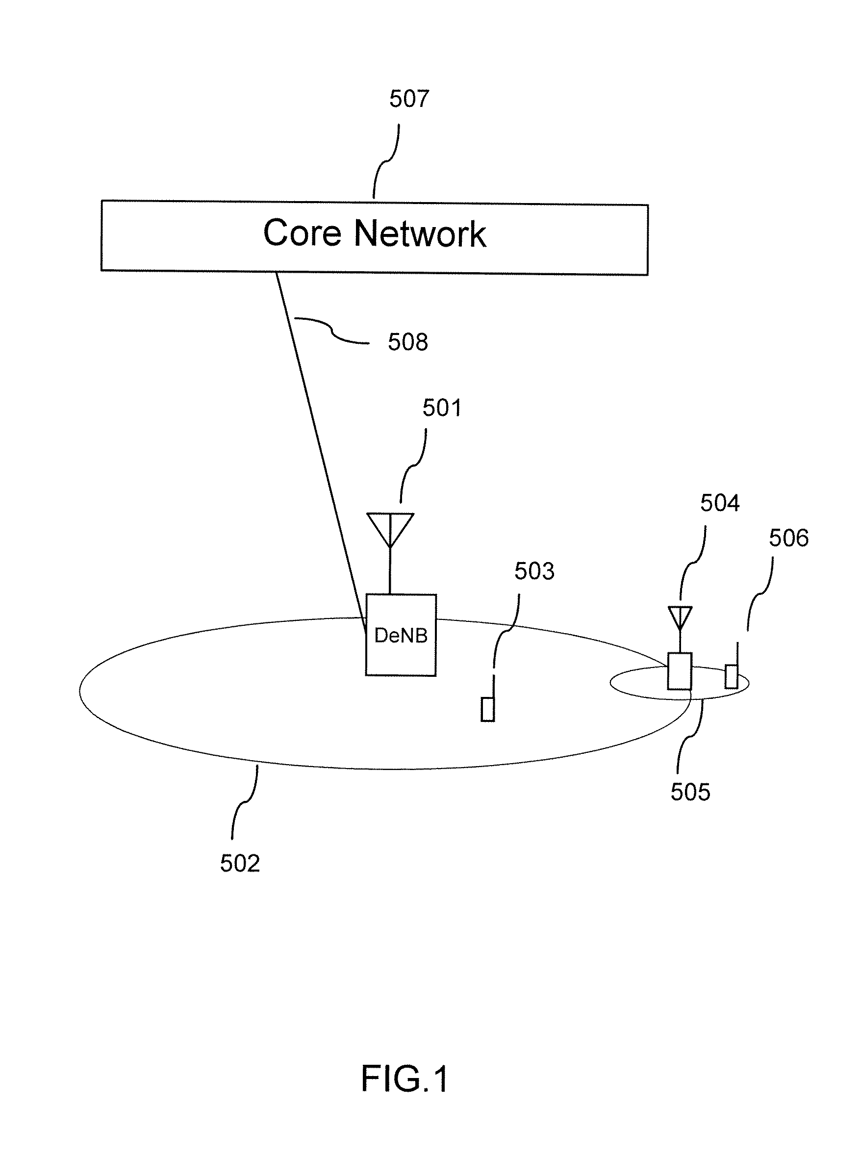
[0090]The relay radio system according to this embodiment includes a donor macro base station 1, a donor macro cell 2, a mobile station 3, a relay femto base station 4, a relay femto cell 5, a mobile station 6, a core network 7, a relay femto base station 8, a relay femto cell 9, a mobile station 10, a macro base station 11, and a mobile station 12.

[0091]It is assumed that the donor macro base station 1 forms the donor macro cell 2, the relay femto base station 4 forms the relay femto cell 5, the relay femto base station 8 forms the relay femto cell 9, and the macro base station 11 forms a macro cell 13.

[0092]The relay femto base station 4 and the relay femto base station 8 according to this embodiment are located within a communication area (or in the vicinity of an edge) of the donor macro cell 2 formed by the donor macro base station 1, and exert the effect particularly w...


PUM


Abstract

Regardless of use of small resource in donor (macro) base station, high throughput in relay femto base station is provided. The relay femto base station transfers data of a C-plane communicated between a core network and a mobile station through the donor macro base station by a radio link, and transfers data of a U-plane through an internet by a wired public line. The relay femto base station measures an interfered power from a neighboring relay femto base station, and notifies the donor macro base station of the measured interfered power, and the donor macro base station adjusts radio packet scheduling so as to prevent interference between the relay femto base stations on the basis of a notified measurement value of the interfered power.

Description

CLAIM OF PRIORITY[0001]The present application claims priority from Japanese patent application JP 2011-001437 filed on Jan. 6, 2011, the content of which is hereby incorporated by reference into this application.BACKGROUND OF THE INVENTION[0002]1. Field of the Invention[0003]The present invention relates to a radio system and a radio communication method, and more particularly to a radio system and a radio communication method which transmit and receive a radio signal between a mobile station and a donor base station and / or a relay base station.[0004]2. Background Art[0005]In recent years, a service area of cellular phones is enlarged, and there are a large number of operators that exceed 99% in population coverage in Japan.[0006]However, a status of indoor area maintenances such as underground cities or tall buildings will be still insufficient.[0007]Because the indoor area maintenance is technically difficult, and expensive, in fact, the area maintenance is difficult.[0008]The in...

Claims


Application Information

Patent Timeline
IPC IPC(8): H04B7/14H04W72/04H04W40/00
CPCH04W24/10H04W72/005H04W84/045H04W72/082H04W84/047H04W72/042H04W72/30H04W72/541H04W72/23
Inventor ISHII, HIROTAKEMORINAGA, YASUTAKA
Owner HITACHI LTD
Why Eureka
Try Eureka