Component cooling channel

a cooling channel and component technology, applied in the direction of marine propulsion, lighting and heating apparatus, vessel construction, etc., can solve the problem of inefficient film cooling

Active Publication Date: 2012-07-12
MIKRO SYSYTEMS INC +1
View PDF14 Cites 29 Cited by
  • Summary
  • Abstract
  • Description
  • Claims
  • Application Information

AI Technical Summary

Problems solved by technology

Film cooling can be inefficient, because so many holes a

Method used


Image

  • Component cooling channel
  • Component cooling channel
  • Component cooling channel

Examples


Embodiment Construction

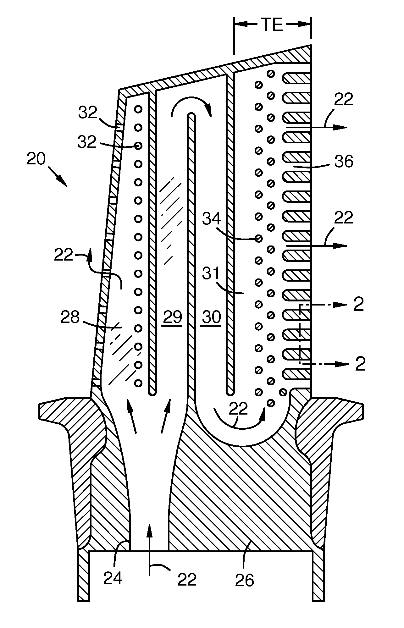
[0011]FIG. 1 is a sectional view of a turbine blade 20. Cooling air 22 from the turbine compressor enters an inlet 24 in the blade root 26, and flows through channels 28, 29, 30, 31 in the blade. Some of the coolant may exit film cooling holes 32. A trailing edge portion TE of the blade may have turbulator pins 34 and exit channels 36. A high-efficiency cooling channel is disclosed herein that is especially useful for exit channels 36.

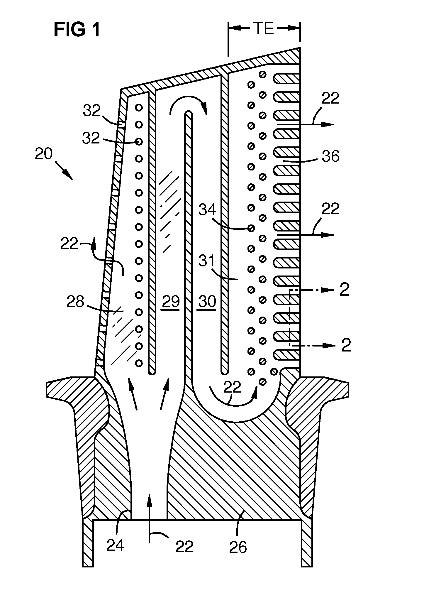
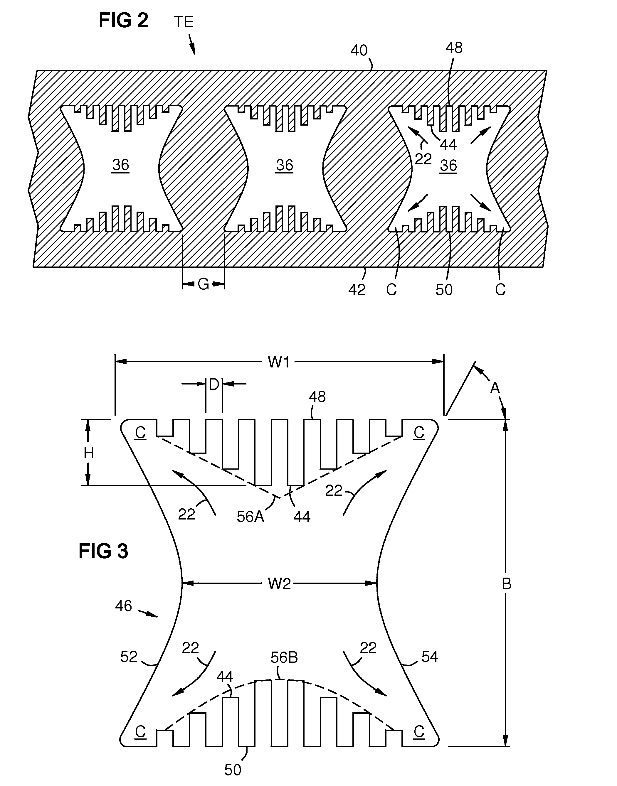
[0012]FIG. 2 is a sectional view of a turbine airfoil trailing edge portion TE taken along line 2-2 of FIG. 1. The trailing edge portion has first and second exterior surfaces 40, 42. Cooling channels 36 may have fins 44 on near-wall inner surfaces 48, 50 according to aspects of the invention. Herein, “near-wall inner surface” means an interior surface of a near-wall cooling channel that is closest to the cooled exterior surface. Gaps G between channels produce gaps in cooling efficiency and cooling uniformity. The inventors recognized that cooling eff...


PUM


Abstract

A cooling channel (36, 36B) cools an exterior surface (40 or 42) or two opposed exterior surfaces (40 and 42). The channel has a near-wall inner surface (48, 50) with a width (W1). Interior side surfaces (52, 54) may converge to a reduced channel width (W2). The near-wall inner surface (48, 50) may have fins (44) aligned with a coolant flow (22). The fins may highest at mid-width of the near-wall inner surface. A two-sided cooling channel (36) may have two near-wall inner surfaces (48, 50) parallel to two respective exterior surfaces (40, 42), and may have an hourglass shaped transverse sectional profile. The tapered channel width (W1, W2) and the fin height profile (56A, 56B) increases cooling flow (22) into the corners (C) of the channel for more uniform and efficient cooling.

Description

FIELD OF THE INVENTION[0001]The invention relates to near-wall cooling channels for gas turbine components such as blades, vanes, and shroud elements.BACKGROUND OF THE INVENTION[0002]Components in the hot gas flow path of gas turbines often have internal cooling channels. Cooling effectiveness is important in order to minimize thermal stress on these components. Cooling efficiency is important in order to minimize the volume of air diverted from the compressor for cooling. Film cooling provides a film of cooling air on outer surfaces of a component via holes from internal cooling channels. Film cooling can be inefficient, because so many holes are needed that a high volume of cooling air is required. Thus, film cooling has been used selectively in combination with other techniques. Impingement cooling is a technique in which perforated baffles are spaced from a back surface of a component opposite a heated surface to create impingement jets of cooling air against the back surface. I...

Claims


Application Information

Patent Timeline
IPC IPC(8): F01D5/18F28F7/00
CPCF01D5/187F05D2240/304F05D2250/13F01D5/18F28F3/048F28F7/02F05D2260/2214
Inventor LEE, CHING-PANGMARRA, JOHN J.MERRILL, GARY B.HENEVELD, BENJAMINE E.KLINGER, JILL
Owner MIKRO SYSYTEMS INC
Why Eureka
Try Eureka