Composite laminated structures and methods for manufacturing and using the same

Active Publication Date: 2012-07-12
THE BOARD OF TRUSTEES OF THE LELAND STANFORD JUNIOR UNIV +1
View PDF9 Cites 48 Cited by
  • Summary
  • Abstract
  • Description
  • Claims
  • Application Information

AI Technical Summary

Benefits of technology

[0012]Accordingly, a need exists to provide laminate structures and methods of manufacturing and using the same, which minimize the various above-mentioned inefficiencies and

Problems solved by technology

Such constraints have traditionally remained unchallenged due to concerns that conventional composite laminated structures will undesirably warp upon cool down from a curing temperature or increased residual stress when the operating temperature changes.
Such lamination processes are generally time and labor intensive as well as being prone to error, requiring precision ordering of the respective composite layers and may result in an unnecessary number of plies, which may contribute to excessive process waste and cost.
Still further symmetric laminates have historically proven cumbersome when seeking to taper the exterior surface of a structure, due at least in part to the desire to maintain symmetry throughout, even

Method used


Image

  • Composite laminated structures and methods for manufacturing and using the same
  • Composite laminated structures and methods for manufacturing and using the same
  • Composite laminated structures and methods for manufacturing and using the same

Examples


Embodiment Construction

[0034]Various embodiments of the present invention now will be described more fully hereinafter with reference to the accompanying drawings, in which some, but not all embodiments of the invention are shown. Indeed, embodiments of the invention may be embodied in many different forms and should not be construed as limited to the embodiments set forth herein. Rather, these embodiments are provided so that this disclosure will satisfy applicable legal requirements. The term “or” is used herein in both the alternative and conjunctive sense, unless otherwise indicated. Like numbers refer to like elements throughout.

Overview

[0035]In general, various embodiments of the present invention dispense with one or more of the various traditionally accepted constraints that govern laminate structure and the methods of making the same. Such constraints, as will be shown, often compromise the integrity and benefits of composite materials, while also rendering prediction of laminate strength extreme...


PUM

PropertyMeasurementUnit
Thicknessaaaaaaaaaa
Thicknessaaaaaaaaaa
Thicknessaaaaaaaaaa

Abstract

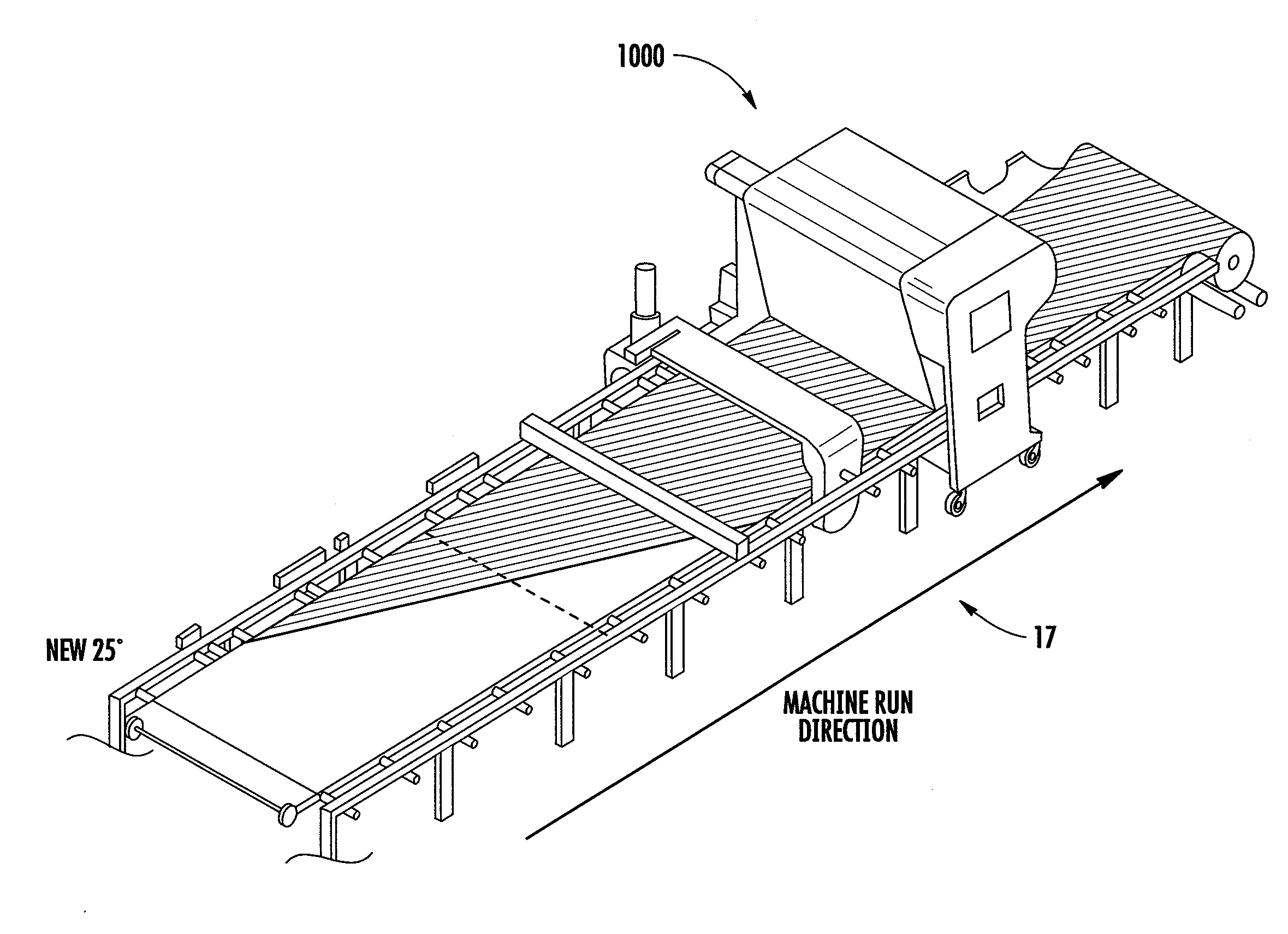
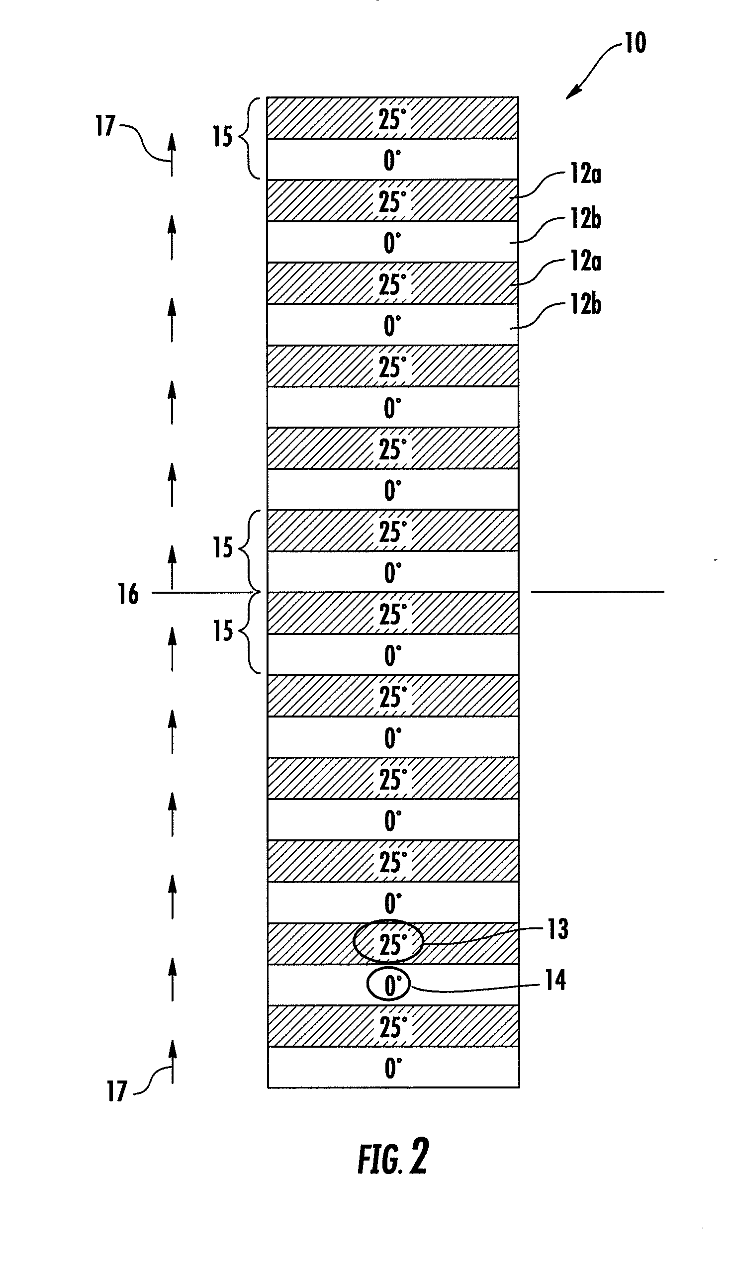
Variously configured sub-laminate modules are provided, which comprise at least a first ply and a second ply, the first ply comprising fibers extending in a first orientation, the second ply comprising fibers extending in a second orientation. The second orientation is offset relative to the first orientation, which offset defines an acute angle between the two orientations. The acute angle is less than 90 degrees and in at least one embodiment, the acute angle is approximately 25°. In certain embodiments, the acute angle further defines an unbalanced structure of the sub-laminate module. In certain embodiments, the first and second plies may be further secured relative to one another in a non-crimped configuration. Composite laminated structures formed from various embodiments of the sub-laminate modules are also provided, at least some of which may be homogenized. Various methods of manufacturing the sub-laminate modules and the composite laminated structures are also provided.

Description

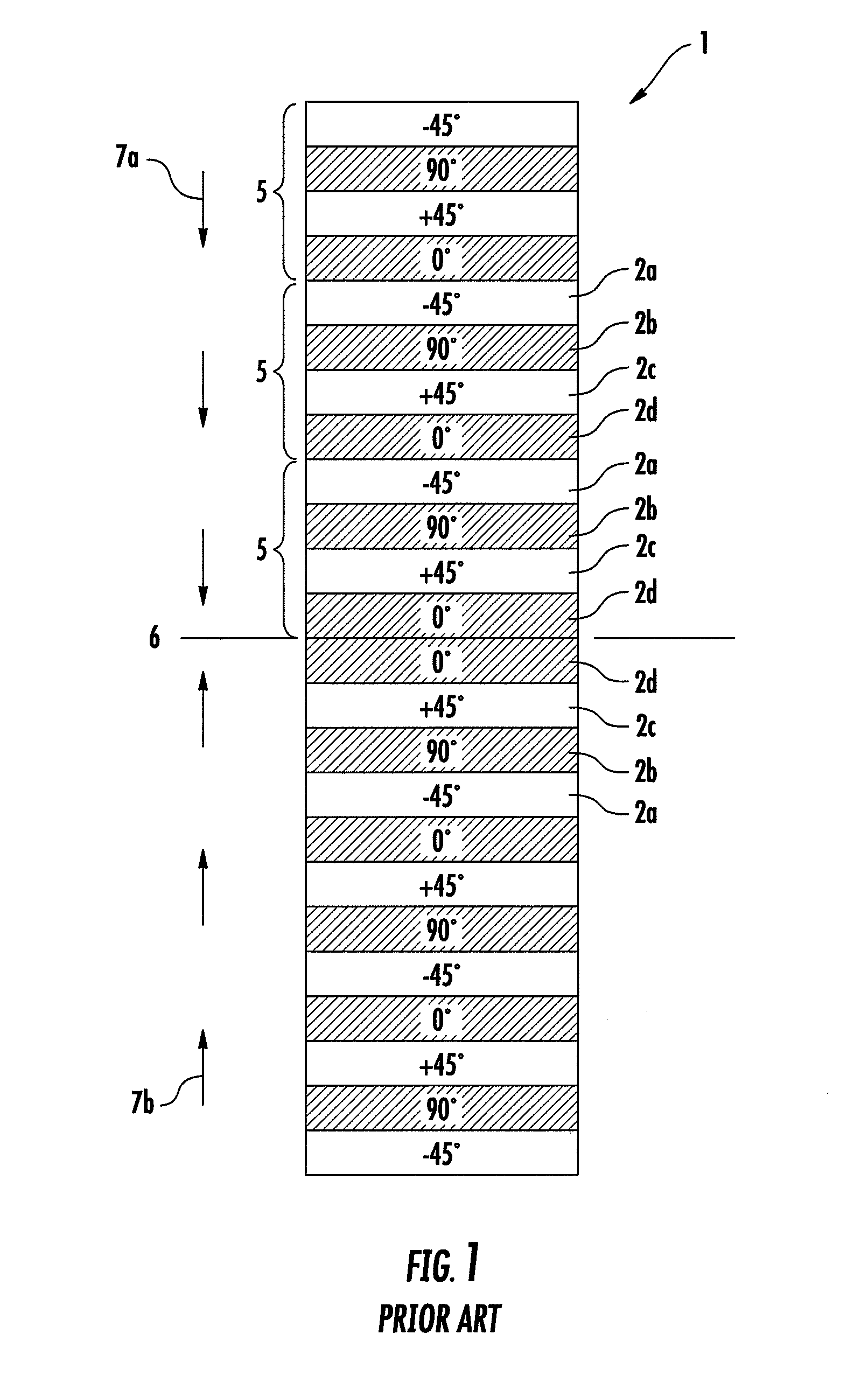
CROSS-REFERENCE TO RELATED APPLICATIONS[0001]This application claims priority to and the benefit of U.S. Provisional Application No. 61 / 432,011, filed Jan. 12, 2011, entitled “Bi-Angle Laminates,” which is incorporated by reference herein in its entirety.BACKGROUND[0002]1. Field of Invention[0003]The present invention relates generally to composite laminated structures, in particular those containing angled ply orientations to achieve desirable improved physical properties, together with methods of manufacturing and using such structures.[0004]2. Description of Related Art[0005]Conventional composite laminated structures are generally designed to emulate the strength characteristics of conventional metal-based laminate materials and as such are constrained to designs having layers of plies that are both symmetrical and balanced. Such conventional structures when so constrained and containing at least three ply layers formed from black carbon fibers, are commonly referred to in the a...

Claims


Application Information

Patent Timeline
IPC IPC(8): B32B5/12B32B37/00B32B38/00D06M17/00
CPCB29C70/202B29C70/30B32B5/12Y10T156/10B32B5/28Y10T428/24124Y10T156/1051B32B5/26B29K2105/0881B29K2307/04B32B5/06
Inventor TSAI, STEVEN W.COGNET, MICHELSANIAL, PHILIPPE
Owner THE BOARD OF TRUSTEES OF THE LELAND STANFORD JUNIOR UNIV
Why Eureka
Try Eureka