Robot and noise removing method for the robot

Active Publication Date: 2012-07-12
SEIKO EPSON CORP
View PDF6 Cites 35 Cited by
  • Summary
  • Abstract
  • Description
  • Claims
  • Application Information

AI Technical Summary

Benefits of technology

[0032]Therefore, it is possible to set the noise filter characteristic to be a characteristic for removing noise peculiar to the inertia sensor. Therefo

Problems solved by technology

Since the robot cannot perform work with high position accuracy while the arm is oscillating, the robot sometimes stays in a standby mode until the arm stops oscilla

Method used


Image

  • Robot and noise removing method for the robot
  • Robot and noise removing method for the robot
  • Robot and noise removing method for the robot

Examples


first embodiment

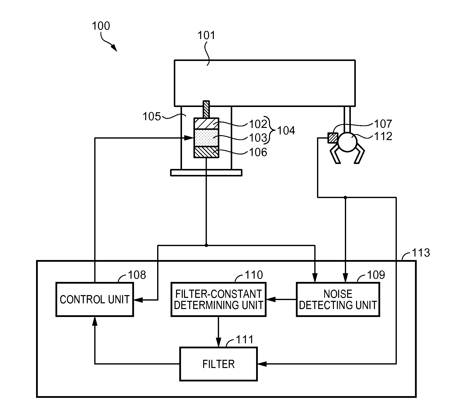
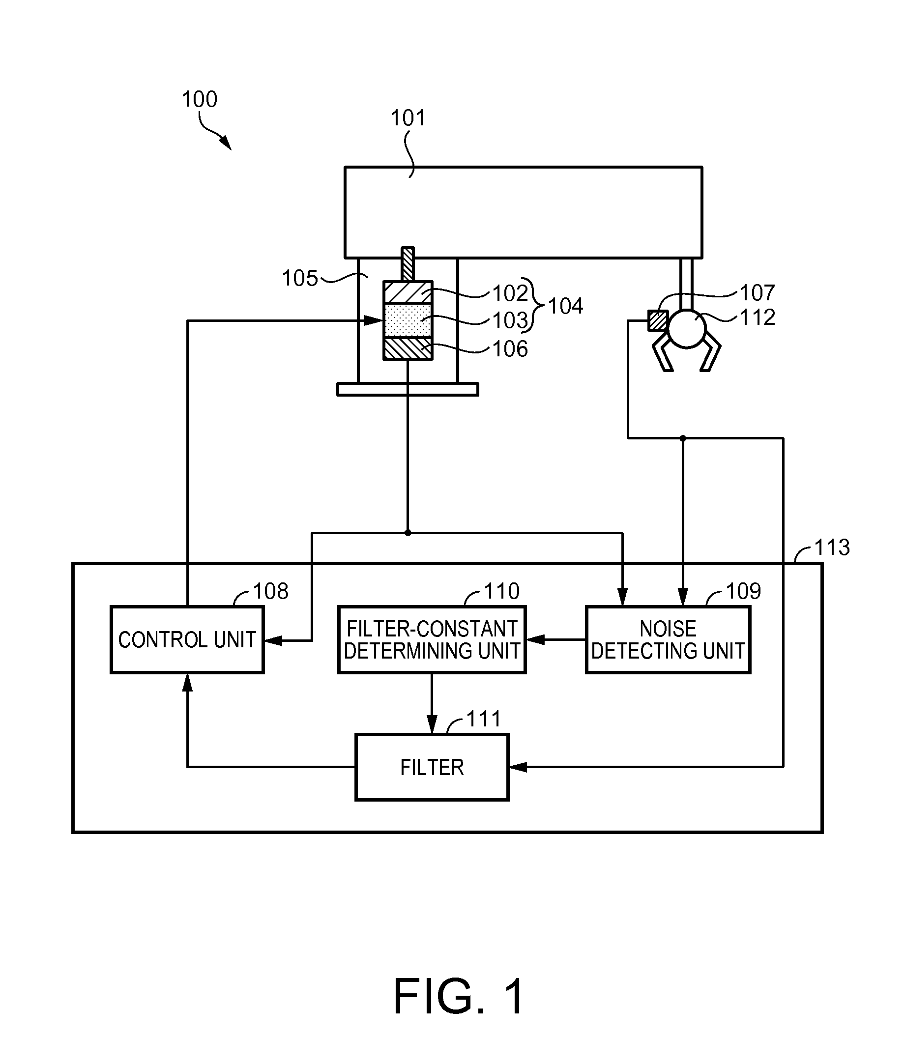
[0041]In a first embodiment, a robot and a characteristic arm control method performed by the robot are explained with reference to FIG. 1 to FIGS. 4A to 4C. FIG. 1 is a block diagram showing a schematic configuration of a robot according to the first embodiment.

[0042]As shown in FIG. 1, a robot 100 includes a base 105.

[0043]An arm coupling section 104 is set on the inside of the base 105. In the arm coupling section 104, an angle sensor 106, a motor 103 functioning as a driving source, and a torque transmitting mechanism 102 are arranged in this order on the same axis. One end of an output shaft of the motor 103 is connected to the angle sensor 106. The angle sensor 106 includes an encoder and detects a pivoting angle of the motor 103. The other end of the output shaft of the motor 103 is connected to an input shaft of the torque transmitting mechanism 102. The torque transmitting mechanism 102 is a reduction gear that is set to a predetermined reduction ratio. Therefore, a pivotin...

second embodiment

[0075]A robot and a characteristic noise removing method performed by the robot according to a second embodiment are explained with reference to FIG. 5 and FIGS. 6A to 6C. This embodiment is different from the first embodiment in that the number of arms is increased from one to two. An explanation of the similarities to the first embodiment is omitted.

[0076]In this embodiment, the number of arms is two as shown in a block diagram showing a schematic configuration according to the second embodiment of FIG. 5. A robot 500 includes a base 509. In the base 509, a first angle sensor 510, a first motor 504 functioning as a driving source, and a first torque transmitting mechanism 503 are arranged in this order one on top of another on the same axis. The first torque transmitting mechanism 503 and the first motor 504 configure a first arm coupling section 505.

[0077]A first arm 501 is connected to an output shaft of the first torque transmitting mechanism 503. The first arm 501 pivots accor...

modification 1

[0093]In the first embodiment, the robot 100 is a robot of a horizontal multi-joint robot form. However, the form of the robot is not limited to this. The method explained above can be used for robots of various forms such as a vertical multi-joint robot, a Cartesian coordinate robot, and a parallel link robot. In this case, noise of an inertia sensor can be removed using a method same as the method explained above.

[0094]In the case of the Cartesian coordinate robot, since an inertia sensor moves linearly, an acceleration sensor is used. In this case, noise peculiar to the acceleration sensor can be detected using data such as a rotation angle of a rotary motor and a moving distance of a linear motor and an output of the acceleration sensor. The noise of the acceleration sensor can be removed using a filter.


PUM


Abstract

A robot includes: an arm driven by a motor; an angle sensor that detects a pivoting angle of the motor; an inertia sensor that detects an inertial force acting on the arm; a noise detecting unit that detects a noise frequency of the inertia sensor from both an output of the angle sensor and an output of the inertia sensor; a filter-constant determining unit that determines a characteristic of a filter from information of the noise detecting unit; and the filter that removes noise of the inertia sensor on the basis of the filter-constant determining unit.

Description

[0001]The entire disclosure of Japanese Patent Application No. 2011-000979 filed Jan. 6, 2011 is expressly incorporated by reference.BACKGROUND[0002]1. Technical Field[0003]The present invention relates to a robot and a noise removing method for the robot and, more particularly, to a control method for the robot.[0004]2. Related Art[0005]When an arm of a robot is actuated and then stopped, the arm oscillates. Since the robot cannot perform work with high position accuracy while the arm is oscillating, the robot sometimes stays in a standby mode until the arm stops oscillating. When the speed of the arm is increased, the oscillation of the arm increases during the stopping event. As a result, the time until the oscillation stops also increases. Therefore, for example, a method of reducing residual oscillation using an inertia sensor in a robot is disclosed in Japanese Patent No. 3883544. The residual oscillation occurs because large elasticity is present between a motor and the dista...

Claims


Application Information

Patent Timeline
IPC IPC(8): B25J9/02
CPCB25J9/1694G05B2219/40549G05B2219/37507G05B2219/37388G01C19/56G05B2219/37008G05B2219/39195G05B2219/40596G05B2219/40597G05B2219/41128B25J13/08B25J9/10
Inventor SASAI, SHIGENORI
Owner SEIKO EPSON CORP
Why Eureka
Try Eureka