

System and method for power grid management
- Summary
- Abstract
- Description
- Claims
- Application Information
AI Technical Summary
Benefits of technology
Problems solved by technology
Method used
Image

Examples
Embodiment Construction
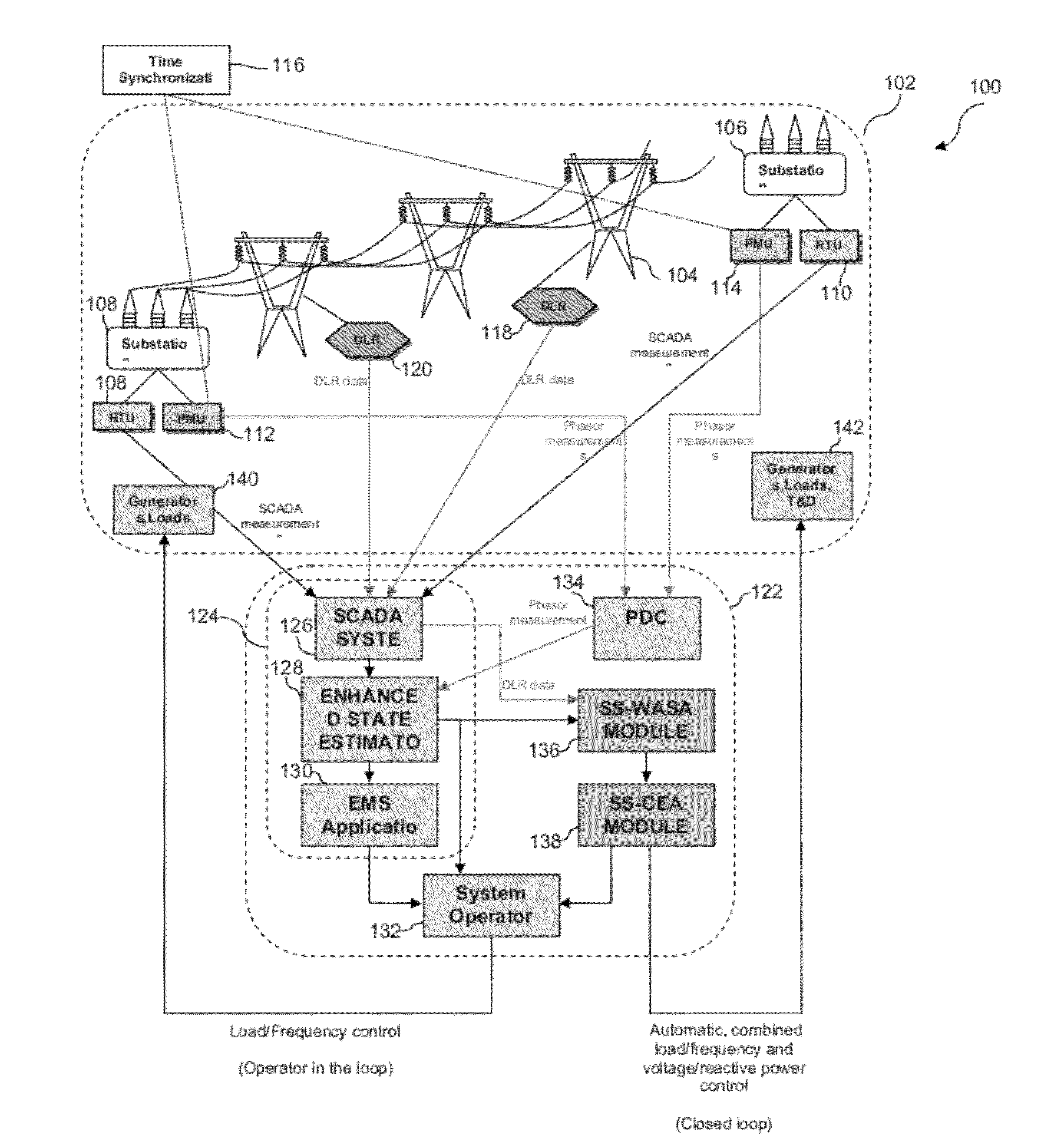
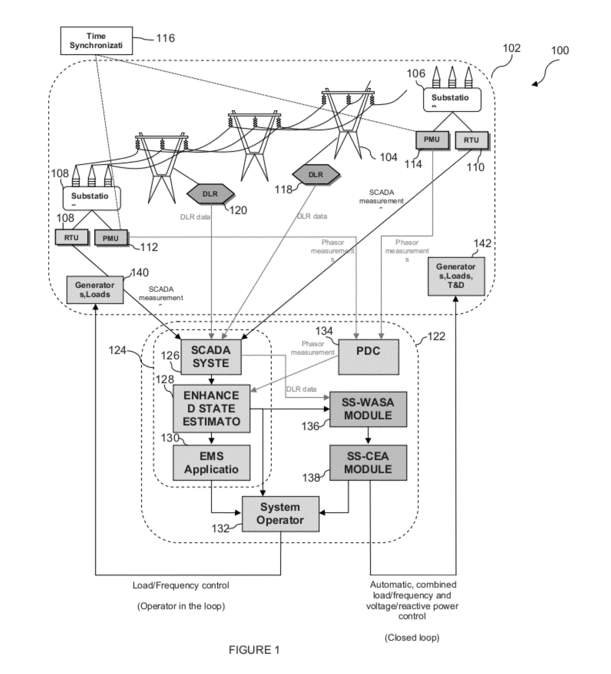
[0045]In one embodiment, the present arrangement provides unique advances in sensing, communications, and computational algorithms for better utilization of the existing and future electric energy assets. In particular, the system builds on the already on-going integration of PMUs and today's SCADA, and the overall effort toward better Wide Area Situational Awareness (WASA). The present system deploys Dynamic Line Rating (DLR) units for estimating actual thermal limits of key transmission lines. The PMU, DLR and SCADA data is integrated into an Enhanced State Estimator (ESE) that forms the basis of WASA. The output of WASA is used by an adaptation module for computing the optimal adjustments of settings on controllable T&D equipment, power plants and responsive demand. Off-line simulations and analysis are carried out to show potential benefits from having better data, as well as from using the data to optimize system-wide control settings as conditions vary. Particular emphasis is ...
PUM
 Abstract
Description
Claims
Application Information