Self-sealing fuel cell and methods of use

Inactive Publication Date: 2012-07-19
CCCIP
View PDF20 Cites 9 Cited by
  • Summary
  • Abstract
  • Description
  • Claims
  • Application Information

AI Technical Summary

Benefits of technology

[0008]Various embodiments provide methods of sealing a penetration into a container. In some embodiments, a method of sealing a penetration in a container includes the steps of holding a visco-elastic sealant material under positive pressure enclosed inside a wall of a container; releasing potential energy enclosed inside the wall upon a penetration through the wall; forcing a flow of the visco-elastic sealant material with the released energy from inside the wall and into the penetration through the wall; filling the penetration through the wall with a portion of the visco-elastic sealant material; achieving an elastic equilibrium of the portion of the visco-elastic sealant material

Problems solved by technology

Various consequences of a pierced container can include loss of a valuable liquid or contamination of an environment by the liquid.
Consequences of pierced fuel tank or fuel cell include loss of fuel, which will cause an engine using the fuel to cease operation.
In battle conditions, a breached fuel tank can lead to the downing of a plane or the abandonment of a la

Method used


Image

  • Self-sealing fuel cell and methods of use
  • Self-sealing fuel cell and methods of use
  • Self-sealing fuel cell and methods of use

Examples


Example

Example 1

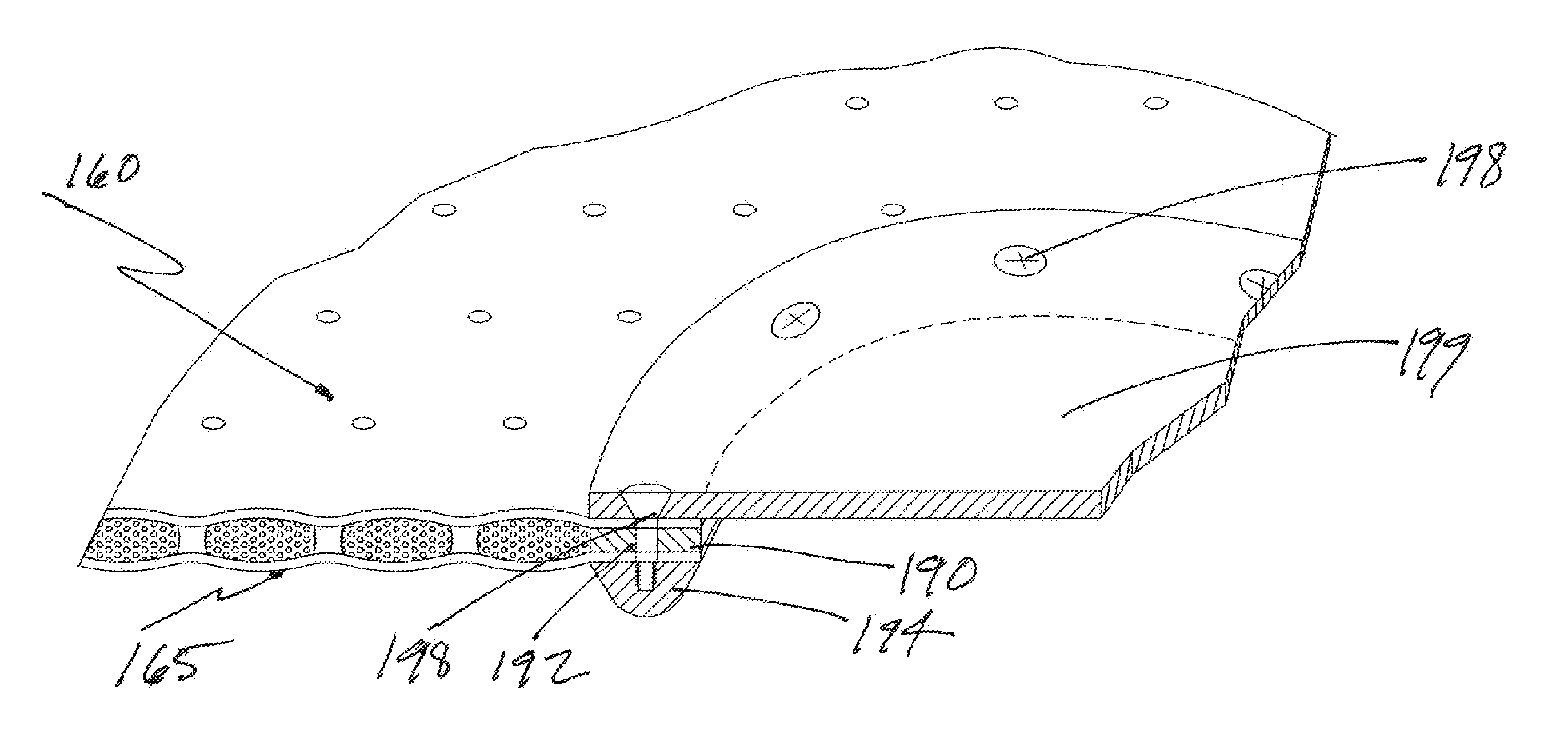
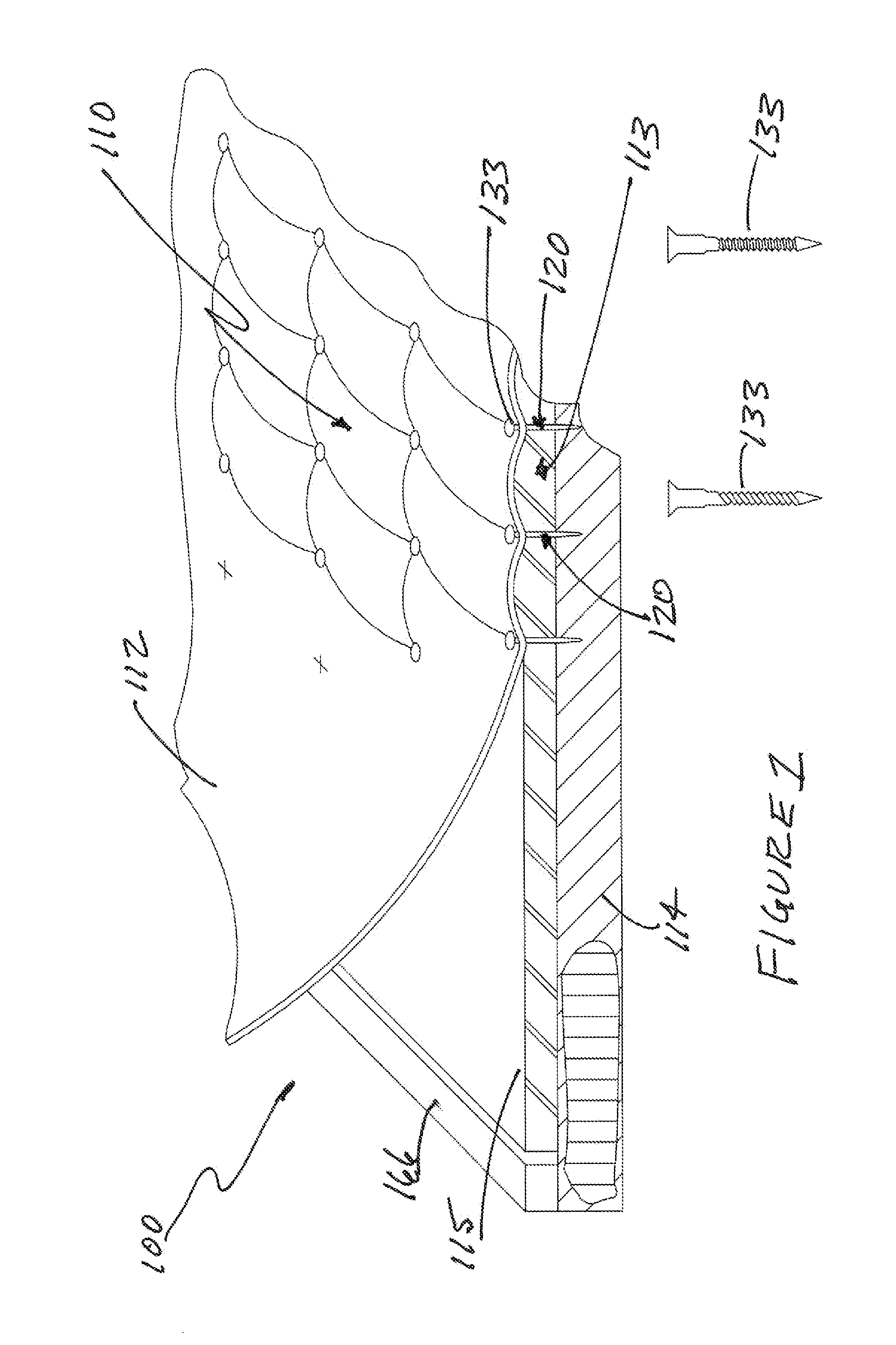
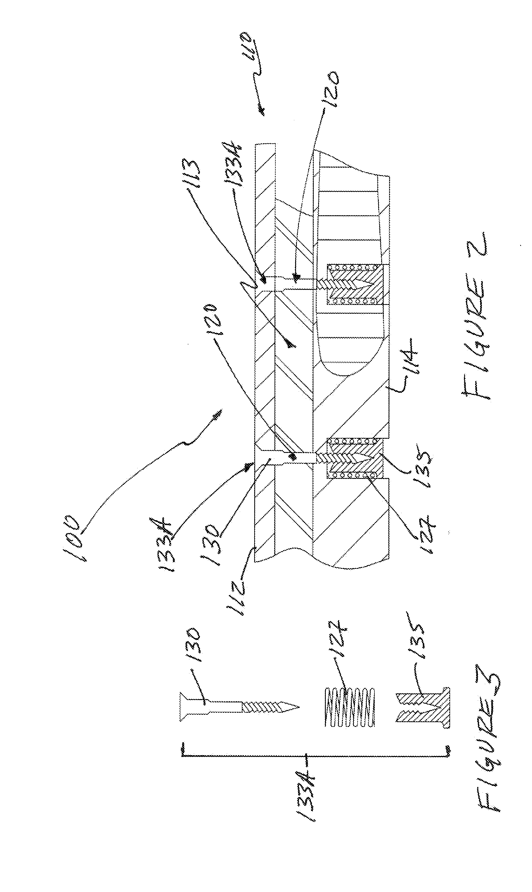
[0083]A pressure reservoir can be created by relying on elastic node connectors, as described herein. One example of constructing a self-sealing system includes the following steps: Cast a 0.02 to 0.4 inch thick wax sheet; Drill uniformly spaced holes of about 0.170 to about 0.35 inch in diameter in wax sheet; Provide a flat, level, substrate; Mix and degas a quantity of uncured elastomer and pour into or onto preset substrate; Lay perforated wax sheet into wet elastomer and allow elastomer to flow through holes; Pour (or laminate) a top layer to complete basic construct; Allow low temperature cure (lower than melting point of wax); Attach a drain / injection port into one corner and a vent in an opposing corner then cure; Melt out wax core; Inject molten sealant material to a prescribed quantity and pressure; Seal drain / injection port and vent then allow to cool.

Example

Example 2

[0084]The self-sealing system constructed in Example 1 was tested with 12 gauge shotgun slugs. Penetration sites of about 0.7 inch in diameter are created. Sealing of penetration sites is instantaneous. Close proximity penetration sites seal instantaneously, if there is a sufficient sealant material and pressure reservoir. Test was conducted at about standard temperature and pressure.

Example

Example 3

[0085]At least fifty specimens of the various cell configurations, including variations in cell structure material and in sealant material, have been ballistically tested with varying degrees of success and hundreds of static and environmental tests have been conducted. Twelve gauge shotgun slugs were used in most tests, which created a large gaping wound, approximately 15 mm diameter. In order to keep costs to a minimum all the early specimens were shot without a liquid backing. Tests for leakage were done by merely placing the mouth over the wound and blowing hard. This was done as quickly as possible after the specimen had been struck, less than five seconds lapse time. In almost all cases the wound had sealed completely. Subsequent tests with a water-filled standpipe placed over the wound showed resistance to blowout of at least a 50-inch (125 mm) head of water, the height limit of the standpipe. It was estimated that depending on wound size; this resistance to blowout ...


PUM


Abstract

Various embodiments provide a self-sealing system comprising a visco-elastic sealant material, an enclosed multi-cell structure surrounding the visco-elastic sealant material, and an integral pressure reservoir configured to maintain positive pressure within the enclosed multi-cell structure and provide potential energy to move the visco-elastic sealant material. In one embodiment, the enclosed multi-cell structure can have first and second skins, and an outer edge configured to contain visco-elastic sealant material between first and second skins. In one embodiment, the enclosed multi-cell structure can also have a plurality of nodes configured to connect first 100 and second skins. In one embodiment, at least one of the nodes has elasticity and can function as a tension spring. In one embodiment, at least one of nodes is loaded with releasable tension to provide a portion of the potential energy to move the visco-elastic sealant material.

Description

CROSS-REFERENCE TO RELATED APPLICATIONS[0001]The present application claims the benefit of and priority to Provisional Patent Application Ser. No. 61 / 433,388, entitled SELF-SEALING FUEL CELL AND METHODS OF USE, filed on Jan. 17, 2011 and incorporates the disclosure of the application by reference.BACKGROUND OF INVENTION[0002]Piercing a container holding a liquid can lead to the liquid escaping from the container. Various consequences of a pierced container can include loss of a valuable liquid or contamination of an environment by the liquid. Consequences of pierced fuel tank or fuel cell include loss of fuel, which will cause an engine using the fuel to cease operation. In battle conditions, a breached fuel tank can lead to the downing of a plane or the abandonment of a land vehicle on the battlefield.[0003]Protecting fuel tanks from enemy fire by the addition of armor may affect the flight worthiness of aircraft or the mobility of a land vehicle. Accordingly, retrofitting aircraft...

Claims


Application Information

Patent Timeline
IPC IPC(8): B65D85/84
CPCB60K2015/03065B60K15/03B60K2015/03407
Inventor COOK, RICHARD L.
Owner CCCIP
Why Eureka
Try Eureka