Chemical heat-storage apparatus

Inactive Publication Date: 2011-02-24
PANASONIC CORP
View PDF10 Cites 3 Cited by
  • Summary
  • Abstract
  • Description
  • Claims
  • Application Information

AI Technical Summary

Benefits of technology

[0009]In the above-mentioned chemical heat-storage apparatus of the present invention, the water supplied through the water flow path to the inside of the container reacts with the heat storage material while moving upward in the container. Since the water flow path is provided below the heat exchanger, the heat storage material present around the heat exchanger can react with water efficiently in the heat release process. Further, since the distribution plate is provided between the opening in the water flow path and the heat exchanger, the water supplied through the opening to the inside of the container moves upward while being dis

Problems solved by technology

However, according to such a configuration in which water is spread on the heat storage material from above, in the case where the heat storage material at the time of heat storage is, for example, in a liquid state or in a solid-liquid coexistence s

Method used


Image

  • Chemical heat-storage apparatus
  • Chemical heat-storage apparatus
  • Chemical heat-storage apparatus

Examples


Example

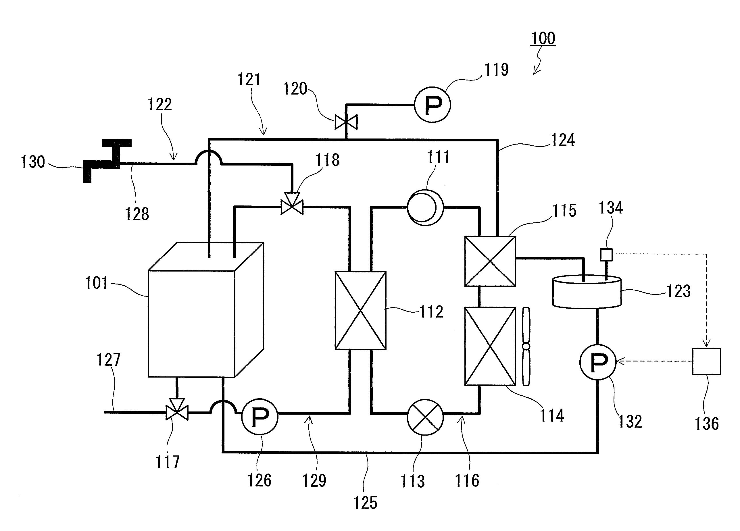
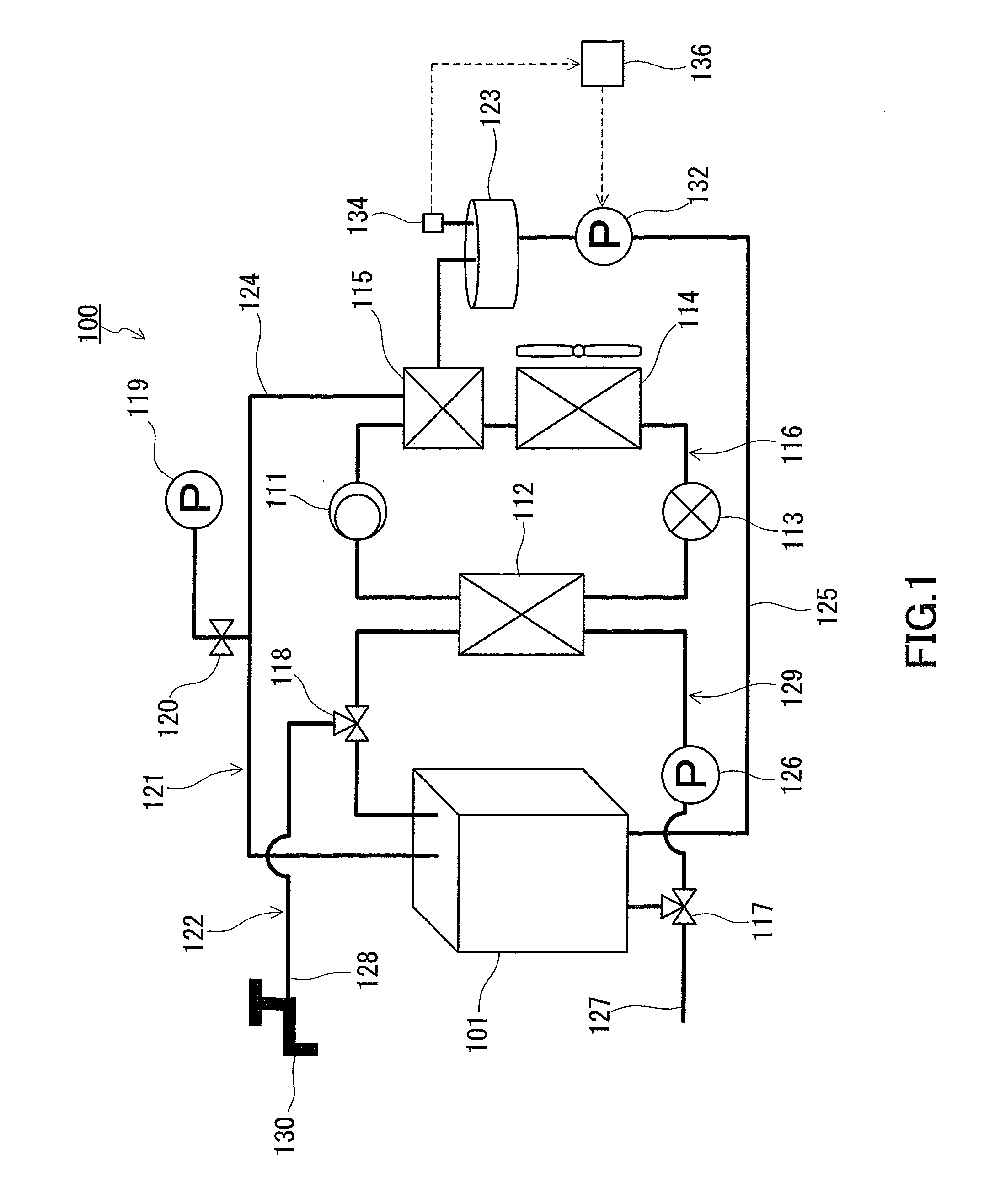
[0026]FIG. 1 is a schematic diagram illustrating a heat storage system according to one embodiment of the present invention. A heat storage system 100 is equipped with a heat pump 116, a heat storage circuit 121 and a heating medium circuit 122.

[0027]The heat pump 116 is equipped with a compressor 111, a heat radiator 112, an expander 113, a first evaporator 114 and a second evaporator 115. These equipments are connected by refrigerant pipes, thereby forming a refrigerant circuit. The second evaporator 115 is used as a condenser 115 for the heat storage circuit 121. The refrigerant circuit is filled with refrigerant such as carbon dioxide and hydrofluorocarbon. The refrigerant that has been compressed in the compressor 111 is cooled in the heat radiator 112. Thereafter, it is expanded in the expander 113, then evaporated in the first evaporator 114 and the second evaporator 115, and returned to the compressor 111 again.

[0028]As a heating apparatus other than the heat pump 116, resis...


PUM


Abstract

A chemical heat-storage apparatus 100 is provided with: a container 202 accommodating a heat storage material 210 that has a higher specific gravity than water and exothermically reacts with water; a heat exchanger 209 that is provided inside the container 202 and that gives heat to the heat storage material 210 in a heat storage process as well as absorbing heat from the heat storage material 210 in a heat release process; a water flow path 204 that has openings 203 opening downwardly and that is provided below the heat exchanger 209 inside the container 202 so as to supply, to the inside of the container 202, the water to react with the heat storage material 210; and a distribution plate 206 that is provided below the heat exchanger 209 inside the container 202 and above the opening 203 and that has a plurality of through holes 205 for introducing the water supplied to the inside of the container 202 from a lower part to an upper part.

Description

TECHNICAL FIELD[0001]The present invention relates to a heat storage apparatus using a chemical reaction of a heat storage material.BACKGROUND ART[0002]Heat storage technology for storing energy is useful as one of energy-saving technologies. In recent years, water heaters or heaters using a CO2 heat pump or a fuel cell cogeneration system have attracted attention. High-density heat-storage technology is under development aiming to average the electricity demand throughout a day by heat storage using midnight power as well as to improve the installation convenience by downsizing these devices.[0003]For example, JP 2005-188916 A and JP 2007-132534 A each describe a latent heat storage apparatus in which heat is stored by direct heat exchange between a heat storage material (latent heat storage material) and a heat exchange medium (oil). In the latent heat storage apparatus of JP 2005-188916 A, oil 2 and a heat storage material 3 are accommodated separately in a container 1a, as indic...

Claims


Application Information

Patent Timeline
IPC IPC(8): F28D20/00
CPCC09K5/063F28D20/003F28D20/021F28D2020/0069Y02E60/145F28D20/025F28D2020/0078Y02E60/142Y02E60/14
Inventor SUZUKI, MOTOHIROKAKIMOTO, ATSUSHISUKAWA, TORUFURUI, MIO
Owner PANASONIC CORP
Why Eureka
Try Eureka