Switched-mode power supply with a damping network

Inactive Publication Date: 2006-03-28
THOMSON LICENSING SA
View PDF5 Cites 1 Cited by
  • Summary
  • Abstract
  • Description
  • Claims
  • Application Information

AI Technical Summary

Benefits of technology

[0012]According to the invention, the damping network has a connection for a second secondary winding, via which energy is transferred from this damping network, for example, to a charge-storage capacitor which is coupled to this secondary winding. The connection is advantageously produced via a rectifying element, for example a diode, which is coupled after the rectifying diode of the second secondary winding, thus preventing this secondary winding from having any reaction on the damping network.
[0013]In a further exemplary embodiment, the diode in the series circuit which is connected in parallel with the rectifier diode of the first secondary winding is not coupled to the charge-storage capacitor

Problems solved by technology

In this case, however, disturbing voltage spikes are produced when the switching transisitor switches off, a

Method used


Image

  • Switched-mode power supply with a damping network
  • Switched-mode power supply with a damping network
  • Switched-mode power supply with a damping network

Examples


Example

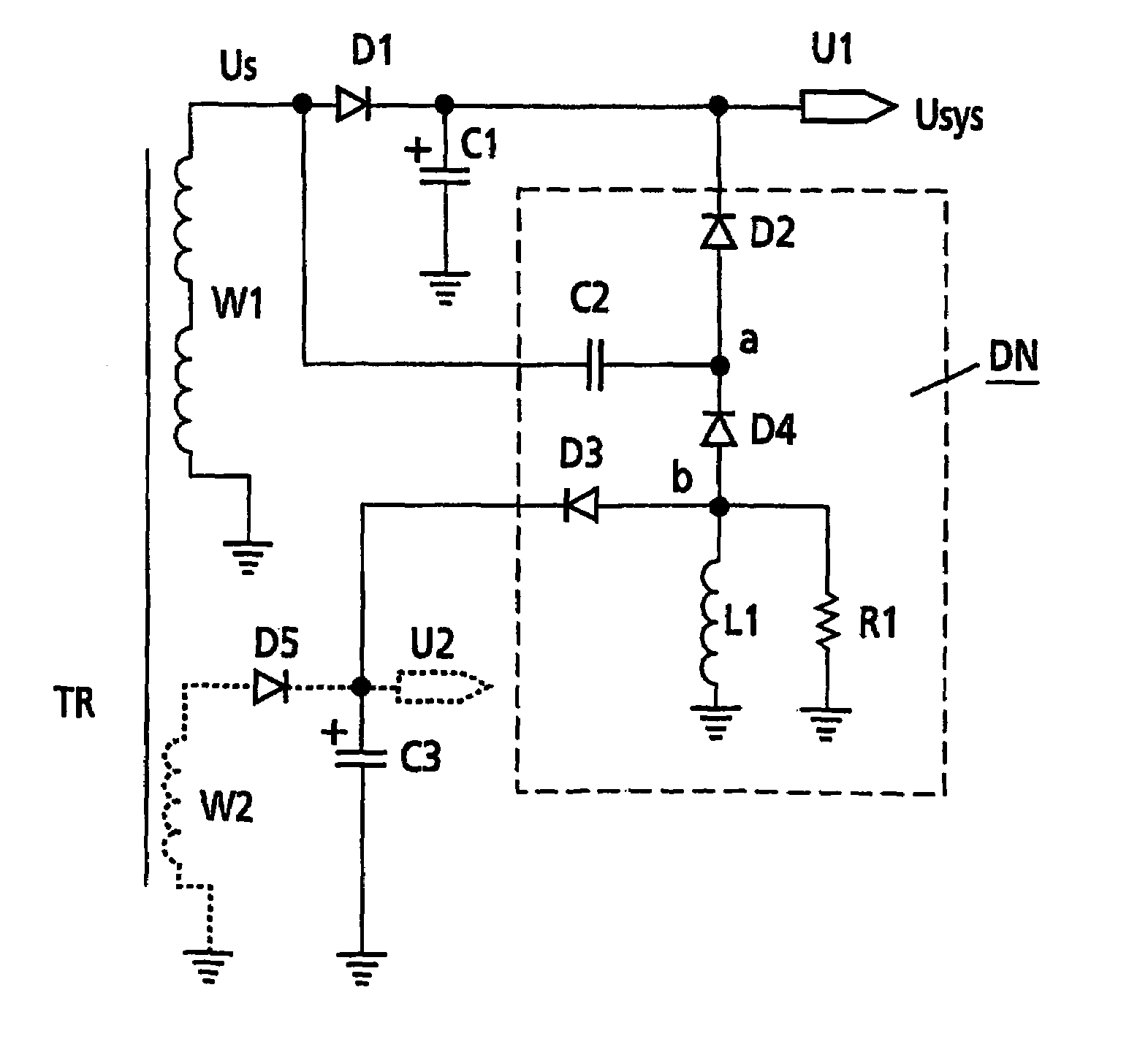
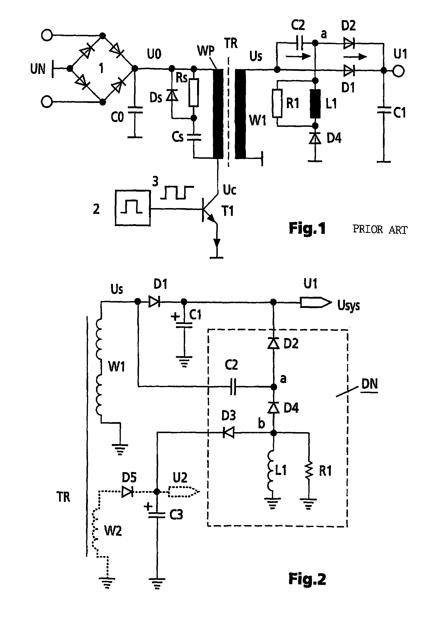
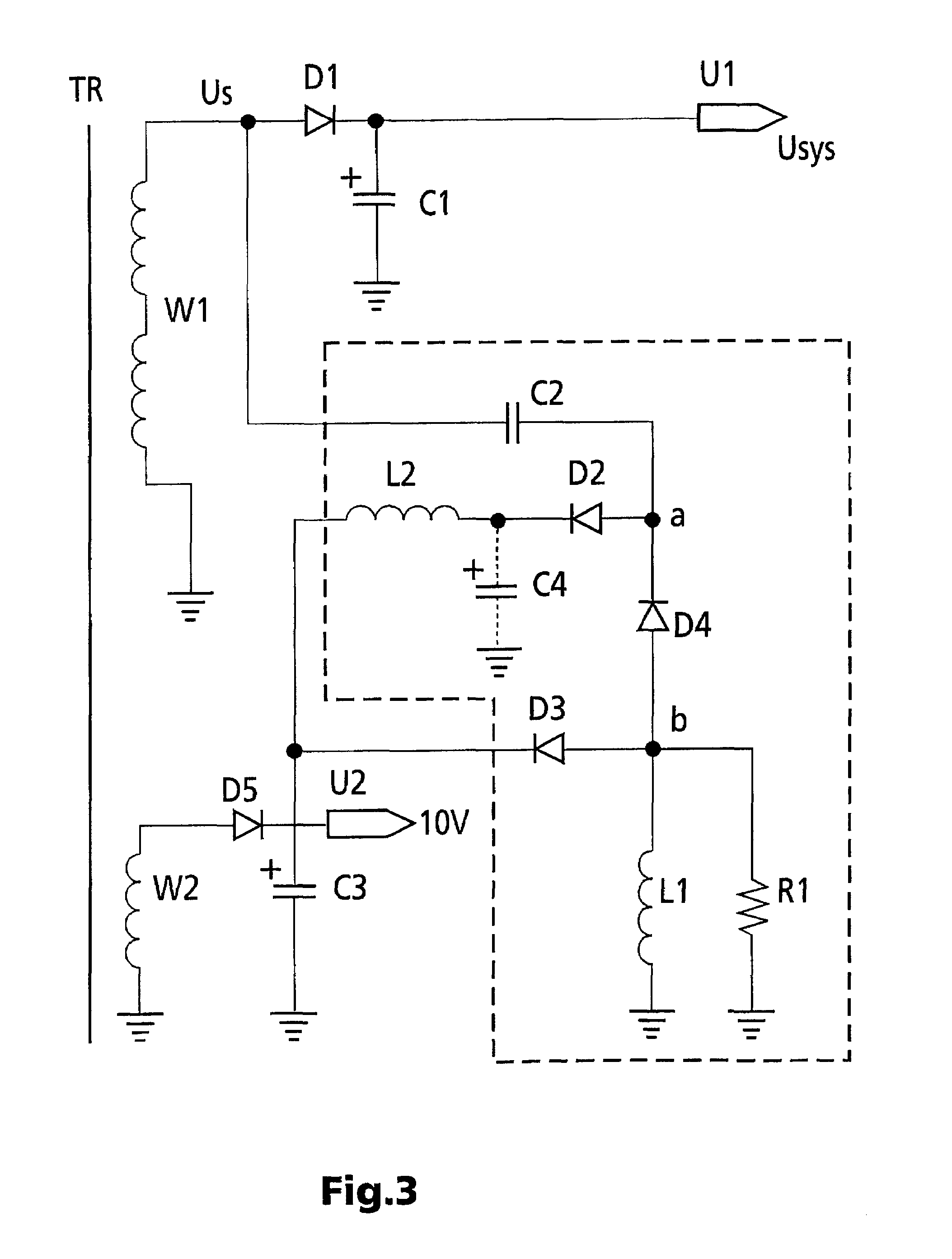
[0018]The switched-mode power supply according to the invention operates, by way of example, on the flyback converter principle, with a switching transistor in series with a primary winding of the transformer, as explained with reference to FIG. 1. However, it is not restricted to this principle. Reference should be made in particular to EP-A-0 695 023 for further details relating to the operation of this switched-mode power supply. FIGS. 2 and 3 show preferred exemplary embodiments of the invention, which relate to an improved damping network arranged on the secondary side. Identical components are thus provided with the same reference symbols. Furthermore, in FIGS. 2 and 3, the part of the switched-mode power supply which is on the primary side as well as further details of the secondary side, in particular regulation elements for voltage stabilization and further secondary windings, are not shown, since these do not relate to the present invention.

[0019]FIG. 2 shows, schematicall...


PUM


Abstract

The switched-mode power supply contains a transformer, a switching transistor in series with the primary winding of the transformer, and a damping network on the secondary side, which has a connection for a further secondary winding via which energy is transferred from this damping network, by way of example, to a charge-storage capacitor which is coupled to this secondary winding. The connection is advantageously produced via a rectifying element, for example a diode, which is coupled after the rectifying diode (D5) for the second secondary winding. In a further exemplary embodiment, the diode in the series circuit, which is connected in parallel with the rectifier diode for the first secondary winding, is not coupled to the charge-storage capacitor for the first secondary winding, but is likewise coupled to the charge-storage capacitor for the second secondary winding.

Description

[0001]This application claims the benefit under 35 U.S.C. § 365 of International Application PCT / EP02 / 07917, filed Jul. 17, 2002, which claims the benefit of German Patent Application No. 101 37 176.4, filed Jul. 31, 2001.FIELD OF THE INVENTION[0002]The invention is based on a switched-mode power supply having a transformer and having a switching transistor, which is connected in series with the primary winding of the transformer. Switched-mode power supplies of this type are used, for example, in televisions, video recorders or computer monitors, and preferably operate as flyback converters, in a power range from about 50 to 150 watts.BACKGROUND OF THE INVENTION[0003]In the flyback converter mode, energy is stored in the transformer during the phase in which the switching transistor is switched on, and this is subsequently transmitted to the secondary side, during the phase in which the switching transistor is switched off. In this case, however, disturbing voltage spikes are produ...

Claims


Application Information

Patent Timeline
IPC IPC(8): H02M5/42H02M3/28H02M1/14H02M1/34H02M3/335
CPCH02M1/34H02M3/335Y02B70/1491H02M2001/346H02M1/346Y02B70/10H02M3/28
Inventor ELGERT, ACHIMTHIBAULT, MICHELLOUVEL, JEAN-PAUL
Owner THOMSON LICENSING SA
Why Eureka
Try Eureka