Electronic ballast and method for operating at least one discharge lamp

a technology of electronic ballast and discharge lamp, which is applied in the direction of lighting apparatus, electrical equipment, light sources, etc., can solve the problems of large negative current amplitude, and achieve the effect of minimising losses

Inactive Publication Date: 2012-07-19
OSRAM GMBH
View PDF6 Cites 2 Cited by
  • Summary
  • Abstract
  • Description
  • Claims
  • Application Information

AI Technical Summary

Benefits of technology

[0007]The object underlying the present invention is therefore to further develop a generic electronic ballast and a generic method such that soft

Problems solved by technology

This results in a larger negative current amplitude when the curren

Method used


Image

  • Electronic ballast and method for operating at least one discharge lamp
  • Electronic ballast and method for operating at least one discharge lamp
  • Electronic ballast and method for operating at least one discharge lamp

Examples


Embodiment Construction

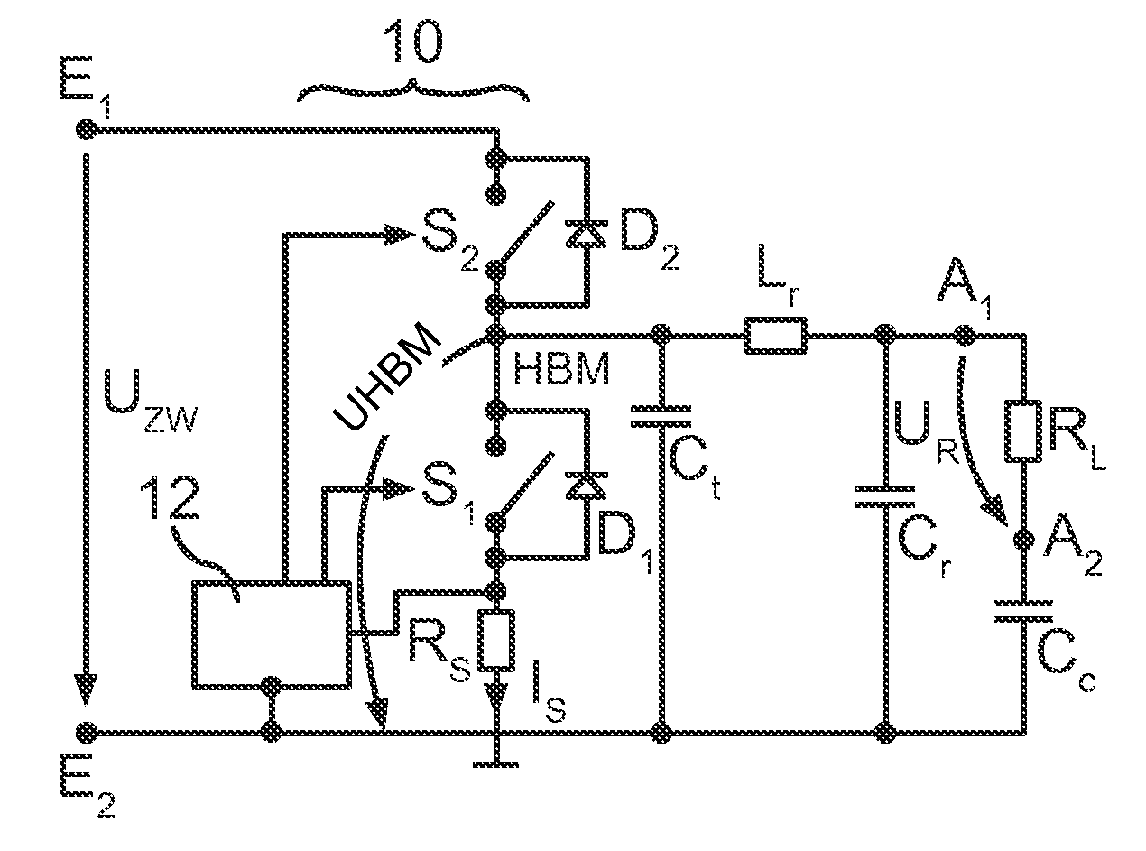
[0023]FIG. 1 schematically illustrates an exemplary embodiment of an electronic ballast according to the invention. Although the invention will now be described using the example of an inverter including a half bridge circuit, it will be clear to the person skilled in the art that the inventive principles are also applicable to a full bridge inverter.

[0024]The electronic ballast shown in FIG. 1 has an input with a first E1 and second input connection E2 for coupling to a DC supply voltage. In this case, this is the so-called DC link voltage UZw which is usually derived from an AC line voltage. Said DC link voltage UZw is applied to an inverter 10 including a first S1 and a second electronic switch S2 in a half bridge arrangement. To control the switches S1, S2, a control device 12 is provided. The control device 12 controls the switches S1, S2 in particular such that the first and the second switch S1, S2 are alternately rendered conducting at a first frequency. For this purpose, th...


PUM


Abstract

In various embodiments, ballast for a discharge lamp includes input and output connections; inverter with bridge circuit with electronic switches and control device for controlling electronic switches, wherein switches are connected in series between input connections, wherein one electronic switch is coupled to first input connection and second electronic switch to second input connection, wherein a bridge midpoint is between electronic switches; including a current measuring device for measuring second electronic switch current; lamp choke series-connected between bridge midpoint and first output connection; capacitor parallel-connected with one of electronic switches; and coupling capacitor; wherein control device is coupled to current measuring device and renders an electronic switch conducting, if negative threshold value is exceeded when electronic switch is rendered nonconducting; or if negative threshold value of current through electronic switch is not exceeded after another electronic switch is rendered nonconducting, wherein control device increases first frequency in second case.

Description

TECHNICAL FIELD[0001]The present invention relates to an electronic ballast for operating at least one discharge lamp, including an input having a first and a second input connection for coupling to a DC supply voltage, an output having a first and a second output connection for coupling to the at least one discharge lamp, an inverter having a bridge circuit with at least one first and one second electronic switch and a control device for controlling at least the first and the second electronic switch such that the first and the second electronic switch are alternately rendered conducting at a first frequency, wherein the first and the second switch are connected in series between the first and the second input connection, wherein the first electronic switch is coupled to the first input connection and the second electronic switch is coupled to the second input connection, wherein a first bridge midpoint is implemented between the first and the second electronic switch, a current me...

Claims


Application Information

Patent Timeline
IPC IPC(8): H05B41/36
CPCH05B41/2828
Inventor STORM, ARWED
Owner OSRAM GMBH
Why Eureka
Try Eureka