Telescoping Rechargeable Powered Pole System with Stand

a technology of telescopic poles and stands, which is applied in the direction of machine supports, transportation and packaging, other domestic objects, etc., can solve the problems of difficult to effectively engineer the wire to allow 360-degree spinning capability without the wire winding up and breaking, and the functionality of the device in the prior art is very limited in adjustability and height in this type of situation, so as to eliminate the fatigue of holding the light, the effect of steady lighting source and incredible searching capabilities

Inactive Publication Date: 2012-07-19
HUDSPETH JAMES DANIEL +1
View PDF2 Cites 22 Cited by
  • Summary
  • Abstract
  • Description
  • Claims
  • Application Information

AI Technical Summary

Benefits of technology

[0022]Thus, it is an object of the invention to provide a lightweight telescoping pole with sufficient internal batteries to power a wide number of various devices. The invention in its current embodiment would include provisions for some form of folding stand or some form of tripod system for quick deployment purposes.
[0023]It is another object of the invention to encase the battery cells inside the top tube of the telescoping pole to provide a ready made and self contained battery box type of arrangement. This convenient configuration is both novel and provides a sleek new way to use many devices that can be powered by the system and quickly deployed in possible remote locations.
[0029]It is finally another object of the invention to provide a 360-degree rotating top tube for quick adjustments and directional control with the top tube fully extended and locked into position with the quick adjustment knobs provided on the telescoping pole. Since the power cells are contained internally, there are no wires to unwind and there is no battery source to deal with as to impede the complete revolution of the top tube with the middle tube quick adjustment knob in the loose position. This configuration works easily on a telescoping pole with a plurality of 3 individual telescoping poles. The middle tube is left in the down position but loose in it's locking collar, and the top tube is fully or partially extended based on required height, and then locked into position with it's locking collar. This allows the top tube while raised in various heights up to full extension to pivot because of the middle tube being loose which provides incredible searching capabilities when coupled with an appropriate light source. When scanning with a light head on the top of the telescoping top tube, fatigue from holding the light is eliminated and a steady lighting source is obtained.
[0030]There are many devices that the Telescoping Rechargeable Powered Pole with Stand System can be adapted to work with in the field. Some of the scenarios that the present embodiment of the invention will provide include several new capabilities. In military situations, a non-lethal super bright blinding light can be attached to the top of a lightweight remote controlled Telescoping Rechargeable Powered Pole with Stand System and triggered remotely and instantly to blind dangerous approaching vehicles at checkpoints along a road. In hunting situations, the ability of the top tube to pivot 360-degrees inside the bottom tube allows the hunter to use a light to scan easily during the night hours—legal in many states for various species of animals. In the case of a video camera installed on the top of the telescoping pole, the direction can quickly be changed for quick field set up or even in a searching mode with high- resolution cameras. In the case of a directional antenna deployment, the antenna can be reoriented very quickly as well. All these devices benefit from the combination of the functionality of the internal battery containment in the top tube to reduce the weight, size and complexity of the device, but also the ability of the design that allows free-spinning directional adjustments of the telescoping pole and the easy set up that this design provides.BRIEF SUMMARY OF THE INVENTION

Problems solved by technology

There has been no prior art with regard to storing rechargeable batteries inside the top pole of a telescoping stack of poles and wiring them to power devices, which could be deployed in an expedient, and efficient manner has not been recognized thus far.
While this looks the same from the outside, it would be difficult to effectively engineer the wire to allow 360-degree spinning capability without the wire winding up and breaking.
U.S. Pat. No. 6,637,904 art depicts a specific type of police light with a structural tripod stand that has many convenient uses specific to the police including the use of the light for the rifle rest, however, functionality of the device in the prior art is very limited in adjustability as well as height in this type of situation.

Method used


Image

  • Telescoping Rechargeable Powered Pole System with Stand
  • Telescoping Rechargeable Powered Pole System with Stand
  • Telescoping Rechargeable Powered Pole System with Stand

Examples


Embodiment Construction

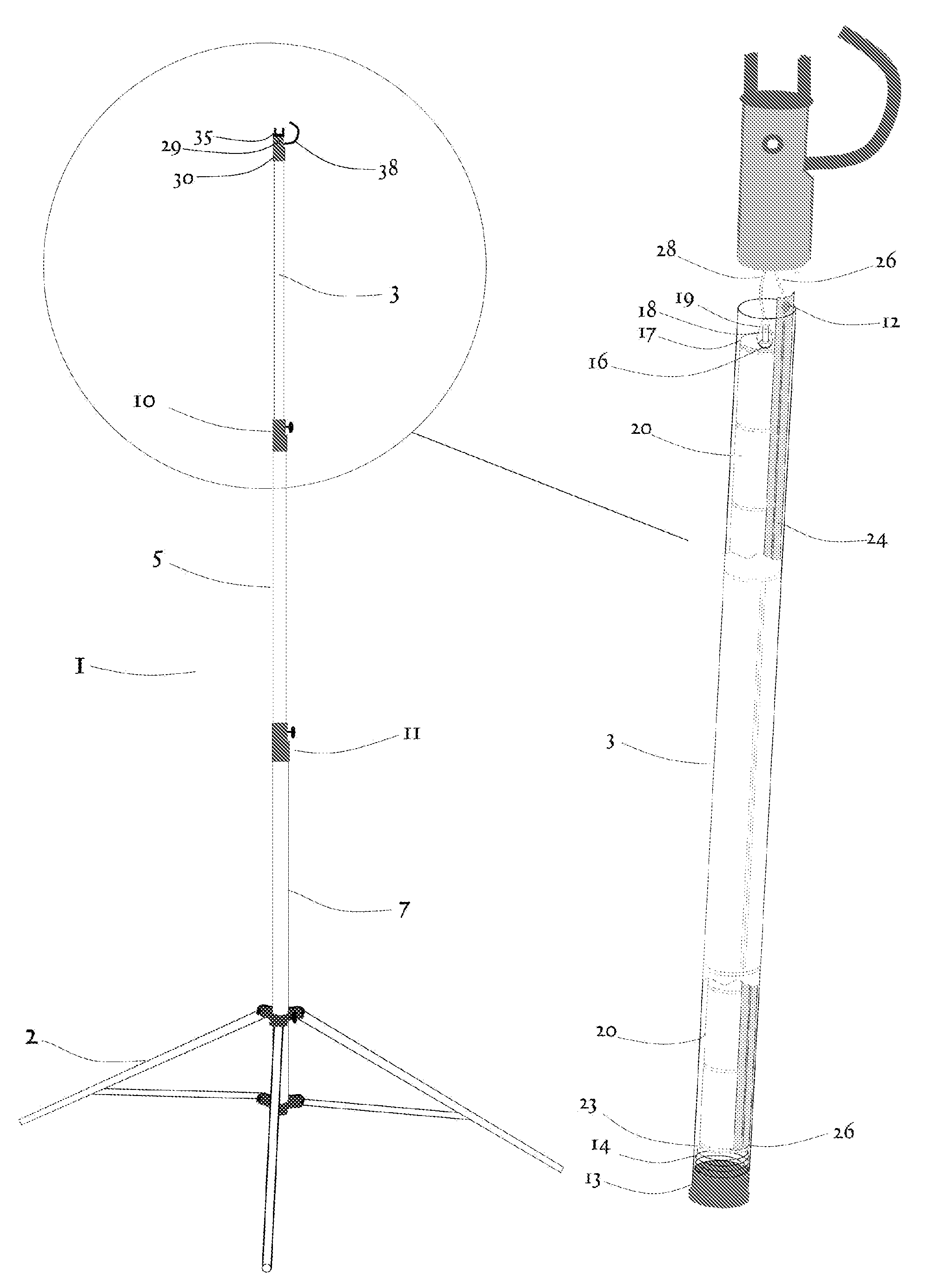
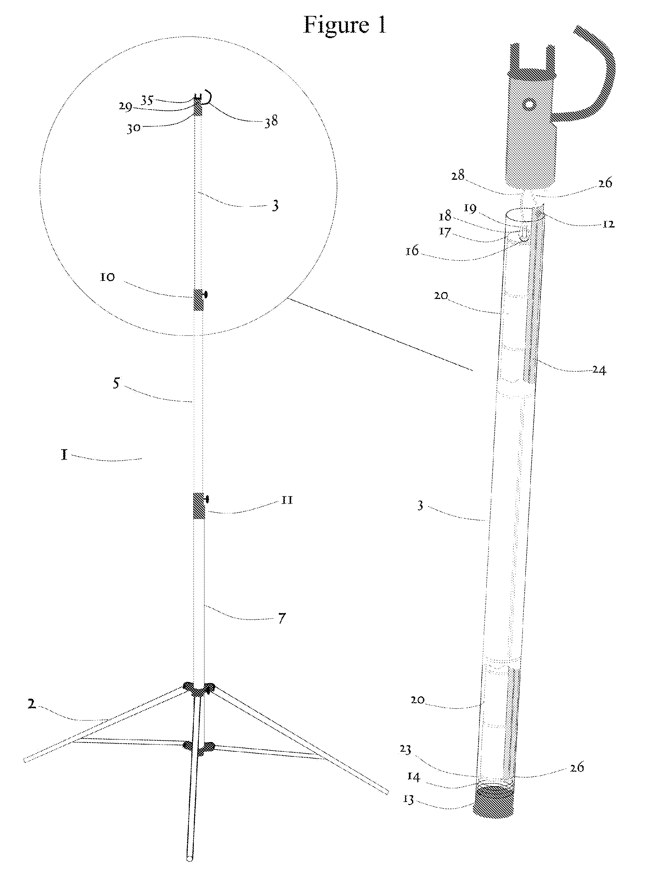
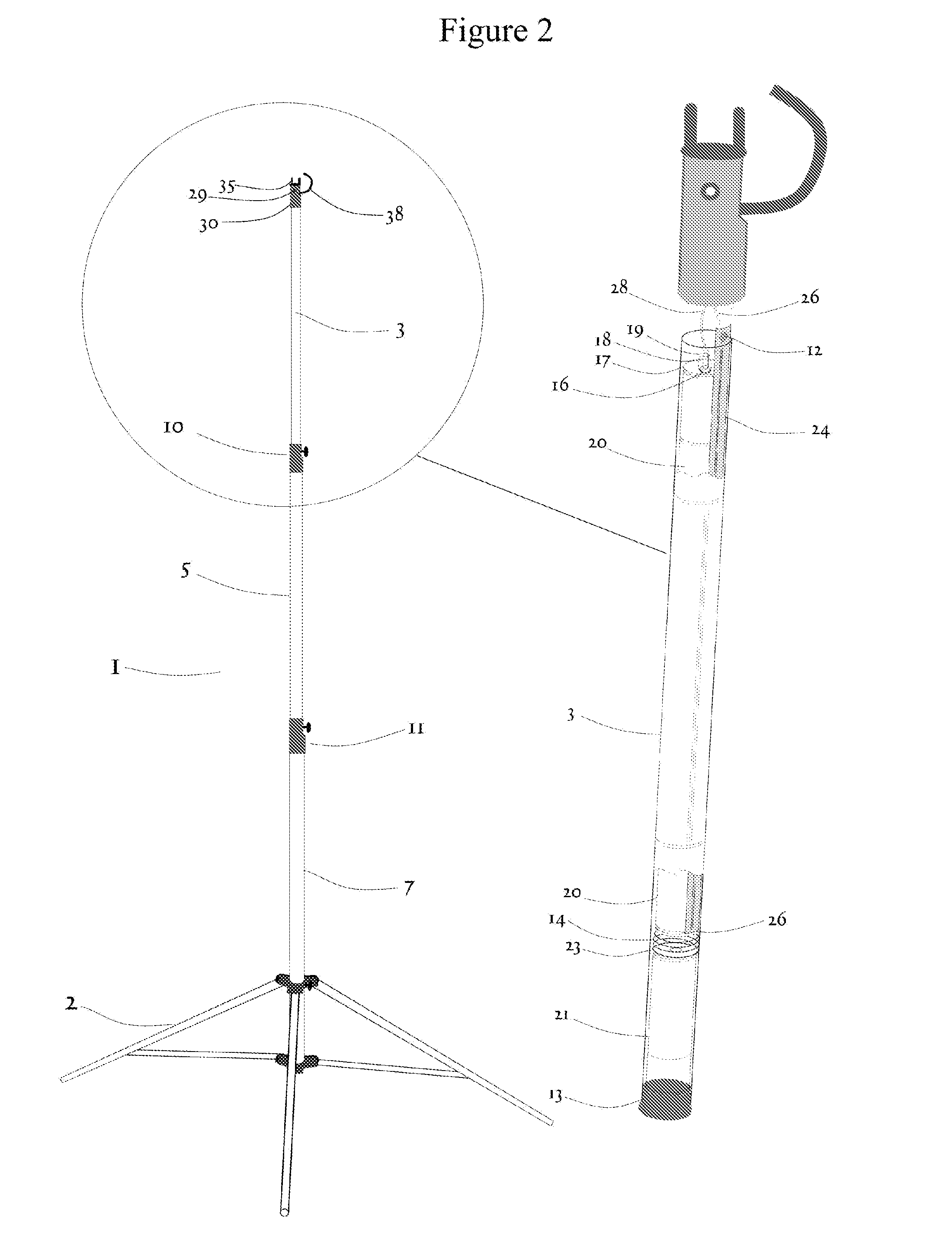
[0038]The present invention is best understood in relation to FIGS. 1 and 2 of the drawings, like numerals being used for like elements of the various drawings.

[0039]FIG. 1 illustrates a frontal view of the present invention with the most relevant components detailed from the overall view with a cutaway view on the right side of the page that details the components detailed in the diagram circle. The backbone of the invention is a telescoping stand system 1, which in the preferred embodiment is designed with an air-cushioned collapsing mechanism as well as an easy to fold tripod stand system 2 constructed of a lightweight materials with sufficient strength to sustain a moderate load at full extension in outdoor conditions. There are many variations on a telescoping stands that would be sufficient to use in this application. The model depicted 1 is of the proper size for a large number of power cells 20. Modifications to this standardized design for a telescoping stand makes possible...


PUM


Abstract

A Telescoping Powered Rechargeable Pole with Stand System 1 with a any one of several devices mounted on the top of the pole that requires a certain level of direct current electric power to maintain it's operation. Usually in a remote place away from any other power source, the stand 2 can be set and the powered telescoping poles 3 and 5 can be raised to gain height for the device mounted on the top of the pole 3. A device mounted directly onto the top cap 30 and powered via a power cable 38 can be powered for a time and then the Telescoping Rechargeable Powered Pole with Stand System can then be recharged through the recharging power port 29. The top cap mount 35 connects the device the top of the pole. The system is powered for a length of time dictated by the size and number of battery cells contained within the top tube 3 of the powered telescoping pole with stand 1. The system is recharged via a suitable charger through the power recharge port 29. A benefit to having the power supply in the top tube 3 allows for 360-degree rotation of the powered device without being encumbered by wires that must reach past the point of contact to the pole structure holding the device. The top tube 3 acts as a support and a battery compartment as well. This tube 3 can be a sealed structural member and provide power to the top device simultaneously and spin freely without wire tangle.

Description

CROSS-REFERENCED TO RELATED APPLICATIONS [0001]Not ApplicableFEDERALLY SPONSORED RESEARCH [0002]Not ApplicableSEQUENCE LISTING OR PROGRAM [0003]Not ApplicableBACKGROUND OF THE INVENTION[0004]1. Technical Field[0005]This invention relates in general to a telescoping pole with a stand mechanism that provides direct current battery power to a source directly suited to be placed on the top of a quickly deployable telescoping stand, specifically a rechargeable battery powered telescoping pole with a minimum plurality of two or more particular length poles that nest one inside the other, the top telescoping pole being initially empty and with sufficient length and girth to encase an appropriate number of rechargeable battery cells to power various types of devices, suited specifically to being deployed quickly in any environment, the power source internalized inside the top tube. This configuration allows a unique 360-degree rotation of the top device and allows for unique searching oppor...

Claims


Application Information

Patent Timeline
Patent Type & Authority Applications(United States)
IPC IPC(8): H02J7/00F16M11/04F16M11/28
CPCF16M11/28F16M11/245
Inventor HUDSPETH, JAMES DANIELMCGILVRAY, CHRIS
Owner HUDSPETH JAMES DANIEL
Why Eureka
Try Eureka