Navigation route planning

a technology of navigation route and planning device, which is applied in the direction of navigation instruments, surveying and navigation, instruments, etc., can solve the problems of distance between, failure of usual route-planning algorithms, and itineraries that may not be available in all areas of interest, so as to reduce the cost

Inactive Publication Date: 2012-07-19
TOMTOM INT BV
View PDF1 Cites 33 Cited by
  • Summary
  • Abstract
  • Description
  • Claims
  • Application Information

AI Technical Summary

Benefits of technology

[0031]The technique may also incorporate a route cost limit, for example, one or more values settable by a user. A route cost refers to any parameter used to judge route performance and, for example, a parameter that one would normally expect to minimise in other route calculation techniques. Example route cost parameters may include, but are not limited to, any of: route distance; expected journey time; financial cost of the route (for example in terms of fuel expended and / or tolls). By using a cost limit, instead of trying to minimise the cost, the technique can develop a sightseeing route less limited by conventional route calculation techniques.

Problems solved by technology

A limitation of conventional navigation and / or routing planning devices is that the route-planning functionality is of course focused on aiding a user to voyage from a departure or start location to a destination location different from the departure location, using appropriate routing criteria (such as trying to minimize a primary “cost” parameter such as journey time or total distance, while also taking account of preferences such as a scenic driving or a scenic walking route, or passing nearby points of interest).
When the start and destination locations are the same, the distance between them is zero, and the usual route-planning algorithms fail.
However, the quality of such itineraries depends on a third party supplier, and itineraries may not be available for all areas of interest.
There is also no facility to fine-tune a pre-prepared itinerary according to an individual user's preferences, nor fit the itinerary to a particular journey time or distance.

Method used


Image

  • Navigation route planning
  • Navigation route planning
  • Navigation route planning

Examples


Embodiment Construction

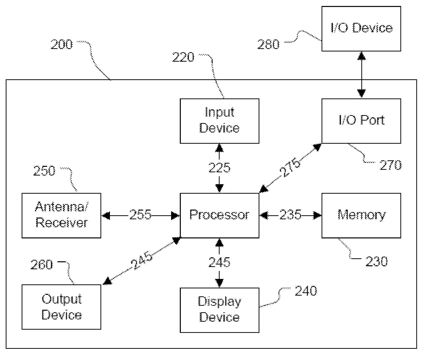
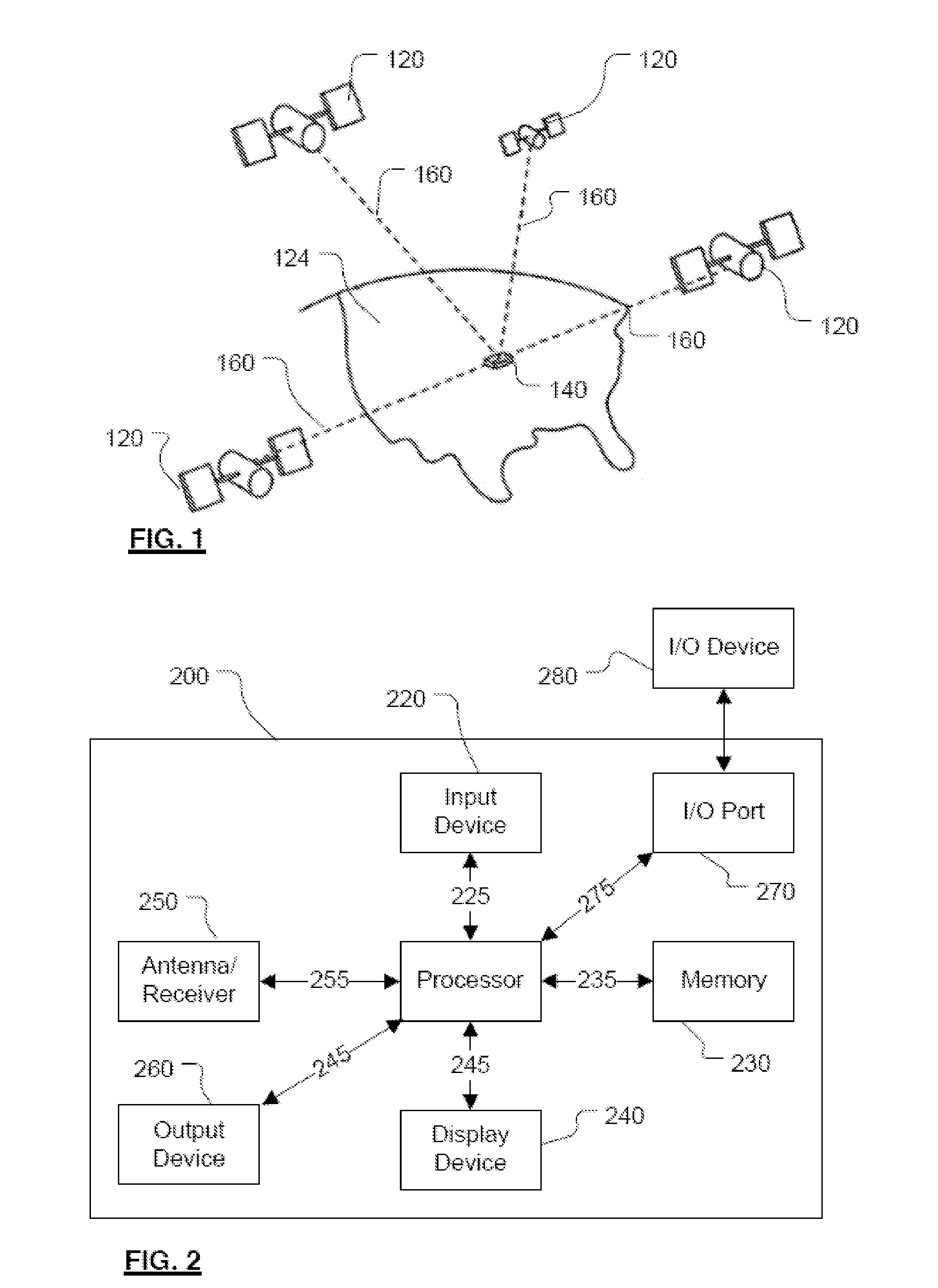
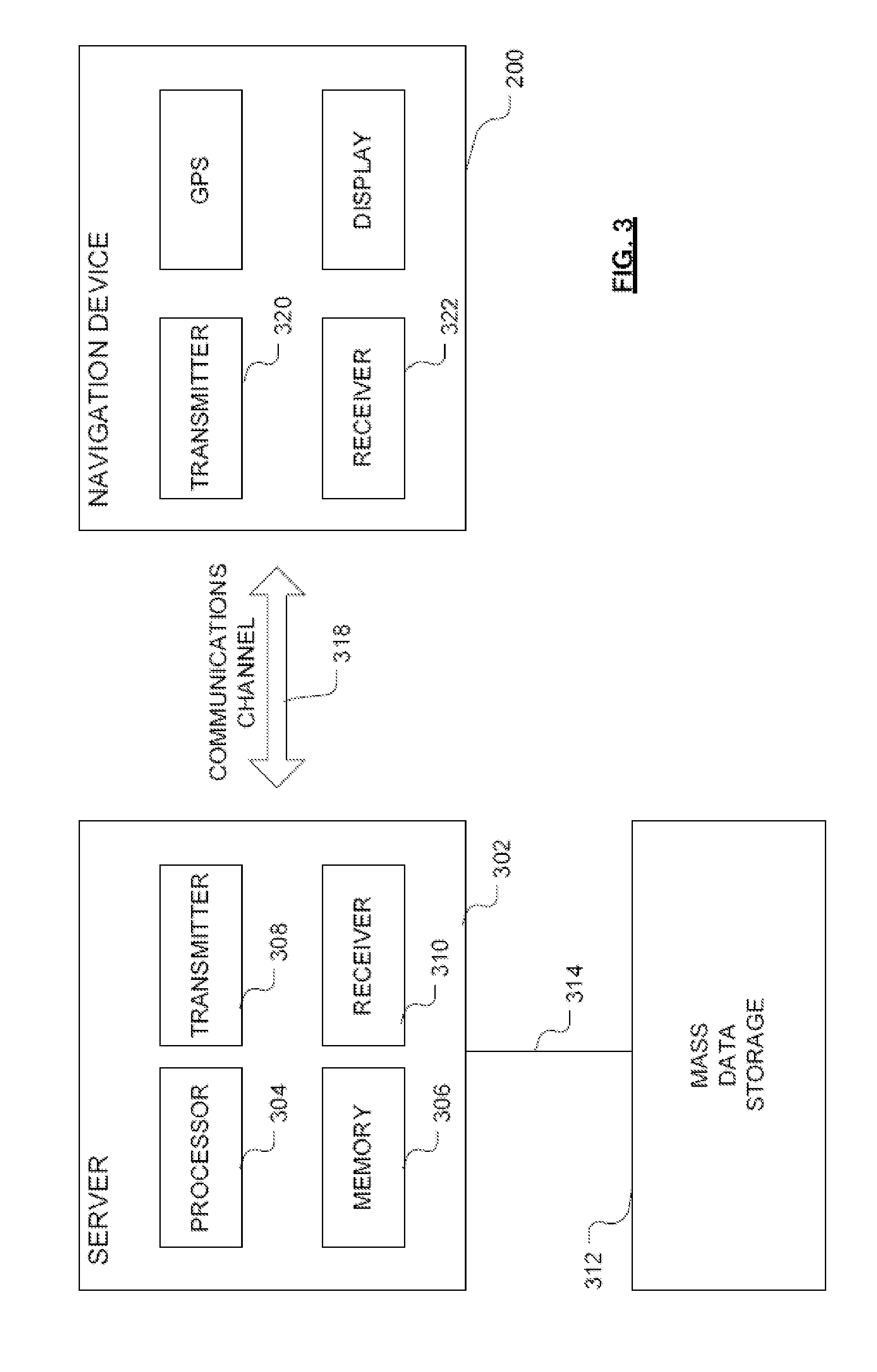
[0056]Preferred embodiments of the present invention will now be described with particular reference to a PND. It should be remembered, however, that the teachings of the present invention are not limited to PNDs but are instead universally applicable to any type of processing device that is configured to execute navigation software so as to provide route planning and / or navigation functionality. It follows therefore that in the context of the present application, a navigation device is intended to include (without limitation) any type of route planning and navigation device, irrespective of whether that device is embodied as a PND, a navigation device built into a vehicle, or indeed a computing resource (such as a desktop or portable personal computer (PC), mobile telephone, client-server system, or portable digital assistant (PDA)) executing route planning and / or navigation software.

[0057]The preferred embodiment implements a technique for calculating a route from a start location...


PUM


Abstract

A technique is disclosed for calculating a sightseeing route from a start location to a destination location. The start location and the destination location may be the same as each other or different. The route is calculated to pass one or more attractors each representing a sightseeing attraction. A digital database resource (500) contains digital map information, the digital map information including a plurality of attractors. The technique comprises (a) determining (550) an initial route from the start location to the destination location, and setting the initial route as a current route; (b) determining (602) for each attractor in a candidate set of the attractors, a relative attraction value that is dependent on a distance between the attractor and the current route; (c) determining (604, 612) which attractor corresponds to a largest attraction value; (d) modifying (620) the current route to include a deviation to the attractor determined at step (c).

Description

FIELD OF THE INVENTION[0001]The present invention relates to the field of navigation route planning devices, and methods associated therewith. Such devices may, for example, be installed as integral vehicle equipment, or may be portable devices usable in-vehicle or in other mobile environments. Alternatively, the device may implemented on a desktop computer, or in a client-server system. The invention may be implemented at least partly within a navigation device and / or at least partly with other equipment with which the navigation device communicates.BACKGROUND TO THE INVENTION[0002]Portable navigation devices (PNDs) that include GPS (Global Positioning System) signal reception and processing functionality are well known and are widely employed as in-car or other vehicle navigation systems.[0003]In general terms, a modern PNDs comprises a processor, memory (at least one of volatile and non-volatile, and commonly both), and map data stored within said memory. The processor and memory...

Claims


Application Information

Patent Timeline
Patent Type & Authority Applications(United States)
IPC IPC(8): G01C21/00
CPCG01C21/343
Inventor BOSCHKER, BREGHT RODERICKTRUM, JEROENLUKASSEN, ROBERT
Owner TOMTOM INT BV
Why Eureka
Try Eureka