Fabric treating machine

a technology of fabric treatment machine and fabric, which is applied in the field of fabric treatment machine, can solve the problems of generating noise and giving a user an unpleasant feeling, and achieve the effects of reducing noise, reducing vibration transfer, and reducing vibration of inner tub and outer tub

Active Publication Date: 2012-07-26
LG ELECTRONICS INC
View PDF10 Cites 0 Cited by
  • Summary
  • Abstract
  • Description
  • Claims
  • Application Information

AI Technical Summary

Benefits of technology

[0009]A fabric treating machine according a present invention comprises a first vibration mitigation part which is disposed between a stator and a bearing unit. Therefore, it is possible to reduce the vibration transfer from the driving unit to the bearing unit, the vibration of an inner tub and an outer tub can be reduced, and a noise can be reduced. In addition, it is possible to improve a reliability of product.
[0010]In addition, a fabric treating machine according a present invention comprises a vibration mitigation part which is disposed between an upper bearing unit and a lower bearing unit. Therefore, it can reduce the vibration transfer from the lower bearing unit to the upper bearing unit, the vibration of an inner tub and an outer tub can be reduced, and a noise can be reduced.

Problems solved by technology

Therefore, there is a problem that the vibration can generate a noise and the noise may give a user an unpleasant feeling.

Method used


Image

  • Fabric treating machine
  • Fabric treating machine
  • Fabric treating machine

Examples


Embodiment Construction

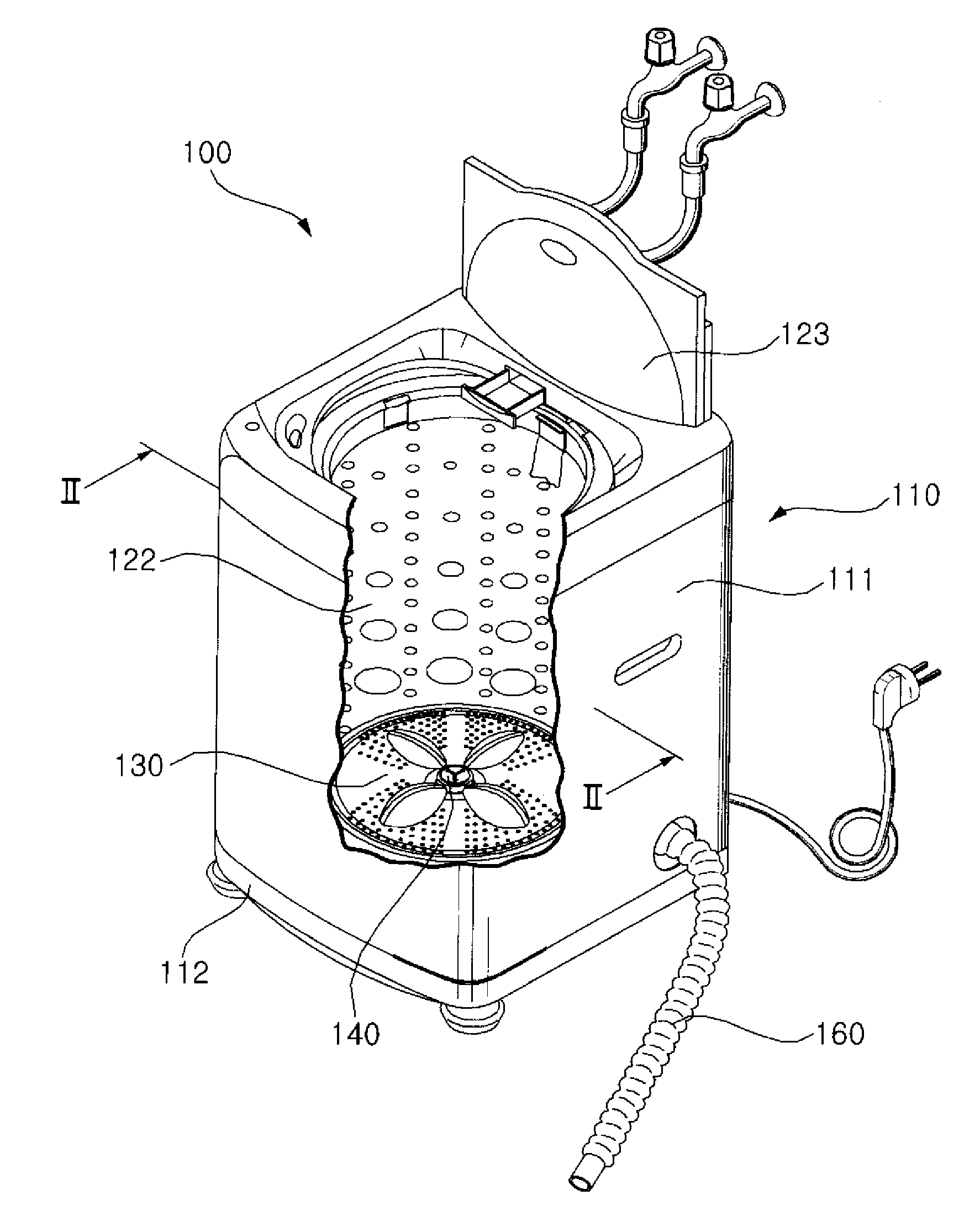
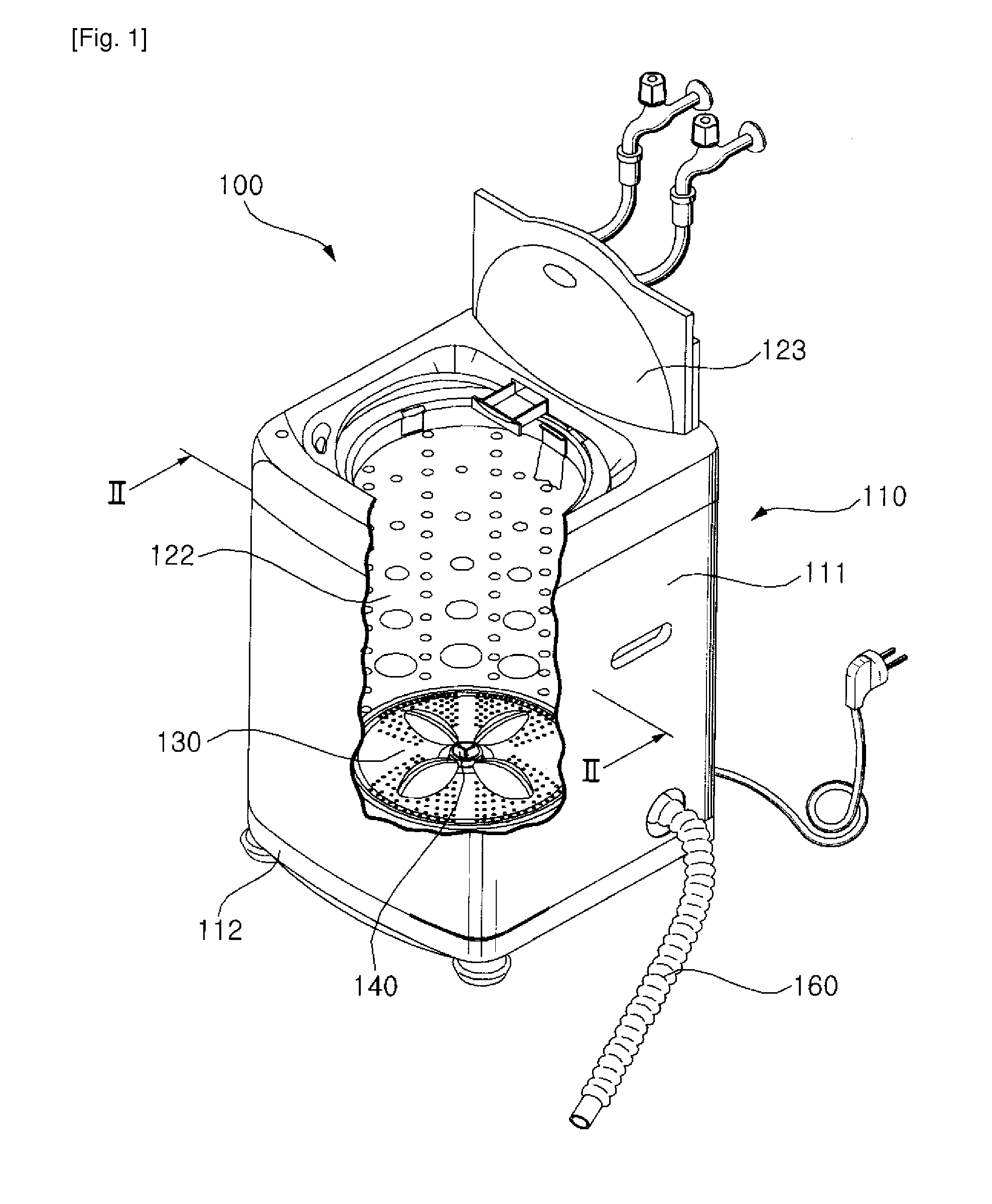
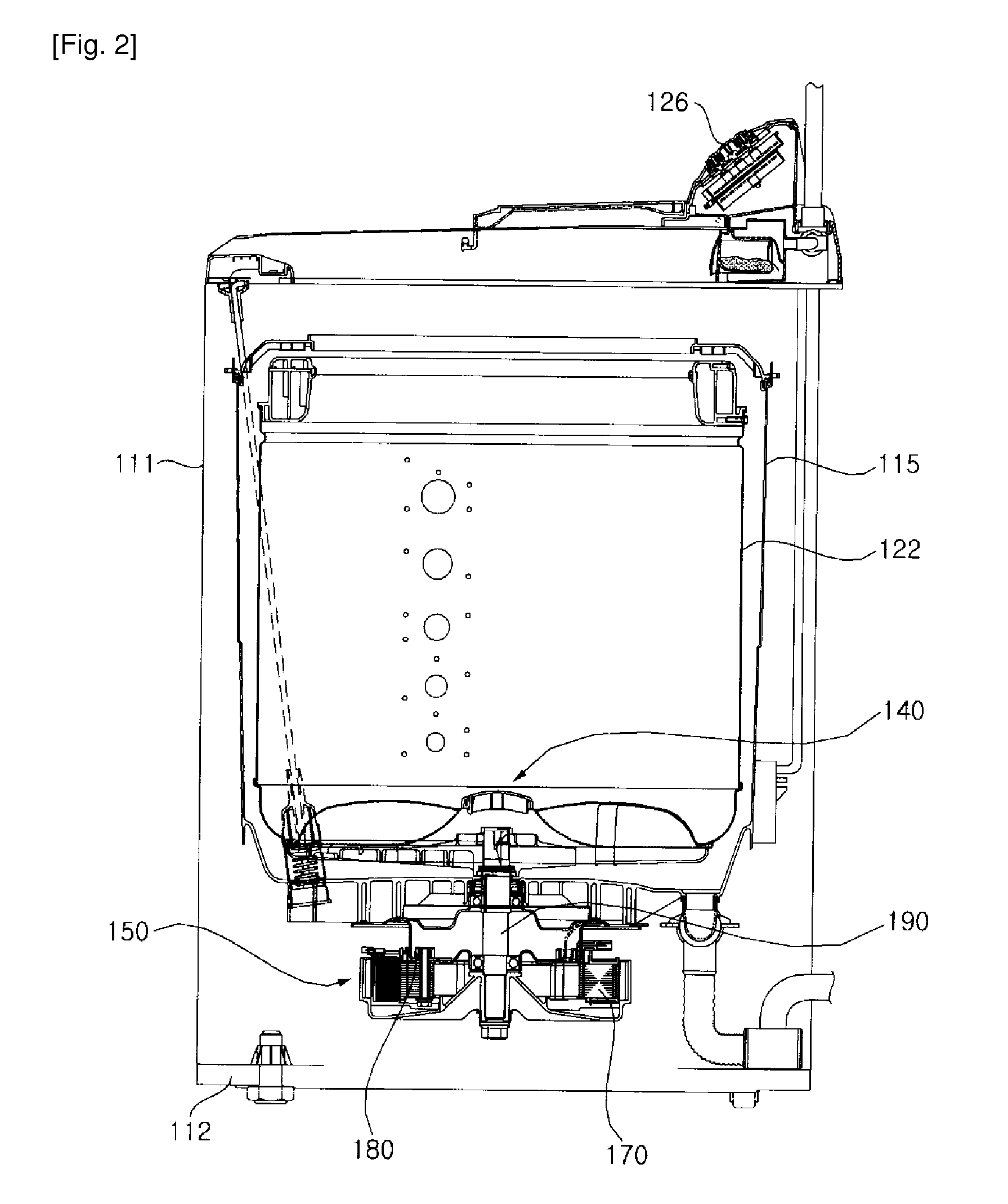
[0032]FIG. 1 is a perspective view which illustrates a fabric treating machine according to the present invention. FIG. 2 is a cross-sectional view taken along line II-II of FIG. 1

[0033]Referring to FIG. 1 and FIG. 2, a fabric treating machine 100 comprises a cabinet 2, an outer tub 115 which is disposed at the inside of the cabinet 100 and contains water, an inner tub 122 which is disposed at the inside of the outer tub 115 and has fabric loaded therein, a driving device 150 which generates a driving power for rotating the inner tub 122, a water supply assembly (not shown) for supplying water to the inside of the outer tub 115 and the inner tub 122, and a drain assembly (not shown) for draining the water contained in the outer tub 115.

[0034]The cabinet 110 comprises a cabinet body 111, a base 112 which is disposed at the bottom of the cabinet body 111, a cover 123 which is disposed at the top of the cabinet body 111 and is connected to the cabinet body 111, a control panel 126 whic...


PUM


Abstract

A fabric treating machine according a present invention comprises a first vibration mitigation part which is disposed between a stator and a bearing unit. Therefore, it can reduce the transfer of the vibration from the driving unit to the bearing unit, and the vibration of an inner tub and an outer tub can be reduced, and a noise can be reduced. Thus, a reliability of product can be improved. Also, a fabric treating machine according a present invention comprises a vibration mitigation part which is disposed between an upper bearing unit and a lower bearing unit. Therefore, it can reduce the vibration transfer from the lower bearing unit to the upper bearing unit, and the vibration of an inner tub and an outer tub can be reduced, and a noise can be reduced.

Description

TECHNICAL FIELD[0001]The present invention relates to a fabric treating machine, and more particularly, to a fabric treating machine for decreasing the vibration transfer from a driving unit to the peripheral parts such as an inner tub.BACKGROUND ART[0002]In general, a laundry treatment is a device for washing or treating fabrics.[0003]A fabric treating machine comprises an inner tub for accommodating fabrics, and a driving unit for generating a driving power to rotate the inner tub. The driving unit comprises a stator for generating an electromagnetic power and a rotator which is rotated by the electromagnetic power. The rotor is connected a rotary shaft which is directly connected the inner tub, so that the rotor transfers a rotary power to the inner tub.[0004]The inner tub and the outer tub vibrate by vibration generated from the rotation of the rotor. Therefore, there is a problem that the vibration can generate a noise and the noise may give a user an unpleasant feeling.DISCLOS...

Claims


Application Information

Patent Timeline
Patent Type & Authority Applications(United States)
IPC IPC(8): D06F37/20D06F37/30D06F37/02
CPCD06F37/20D06F37/24D06F37/206
Inventor KIM, YOUNG JONGLEE, HYUK SOO
Owner LG ELECTRONICS INC
Why Eureka
Try Eureka