Clothes dryer motor support assembly

a technology for dryers and motors, applied in the direction of dynamo-electric machines, washing apparatus, domestic objects, etc., can solve the problems of affecting the operation of the dryer, the resonance of the dryer cabinet, and the vibration of the cabinet floor, so as to reduce the vibration

Inactive Publication Date: 2009-10-01
MABE CANADA
View PDF11 Cites 8 Cited by
  • Summary
  • Abstract
  • Description
  • Claims
  • Application Information

AI Technical Summary

Benefits of technology

[0016]In an alternative embodiment, the support portion comprises at least one material more rigid than the floor of the cabinet for reducing vibration transmitted from the motor to the cabinet floor via the support portion.

Problems solved by technology

Clothes dryer motors produce a substantial amount of vibration which may be transmitted to the cabinet floor.
This vibration produces noise as the cabinet vibrates.
In some cases, the motor vibration may cause the dryer cabinet, or more specifically, the cabinet floor, to resonate.
Resonance can generate loud unwanted noise.
Vibration and noise are very displeasing to a user of the clothes dryer.
However, the raised floor portion takes up space inside the dryer cabinet.
However, these methods may not overcome the problem of resonance.
Further, the addition of rubber insulators to the motor assembly takes up space inside the dryer cabinet and requires the use of additional materials to be used for insulation.
Apparatus such as these may not solve the problem of resonance and once again include additional insulating materials, which can increase cost and assembly time.
Further, the placement of an insulating ring between the motor shaft bearing and the motor mount requires complicated assembly and thus increases costs associated with time and labour.

Method used


Image

  • Clothes dryer motor support assembly
  • Clothes dryer motor support assembly
  • Clothes dryer motor support assembly

Examples


Embodiment Construction

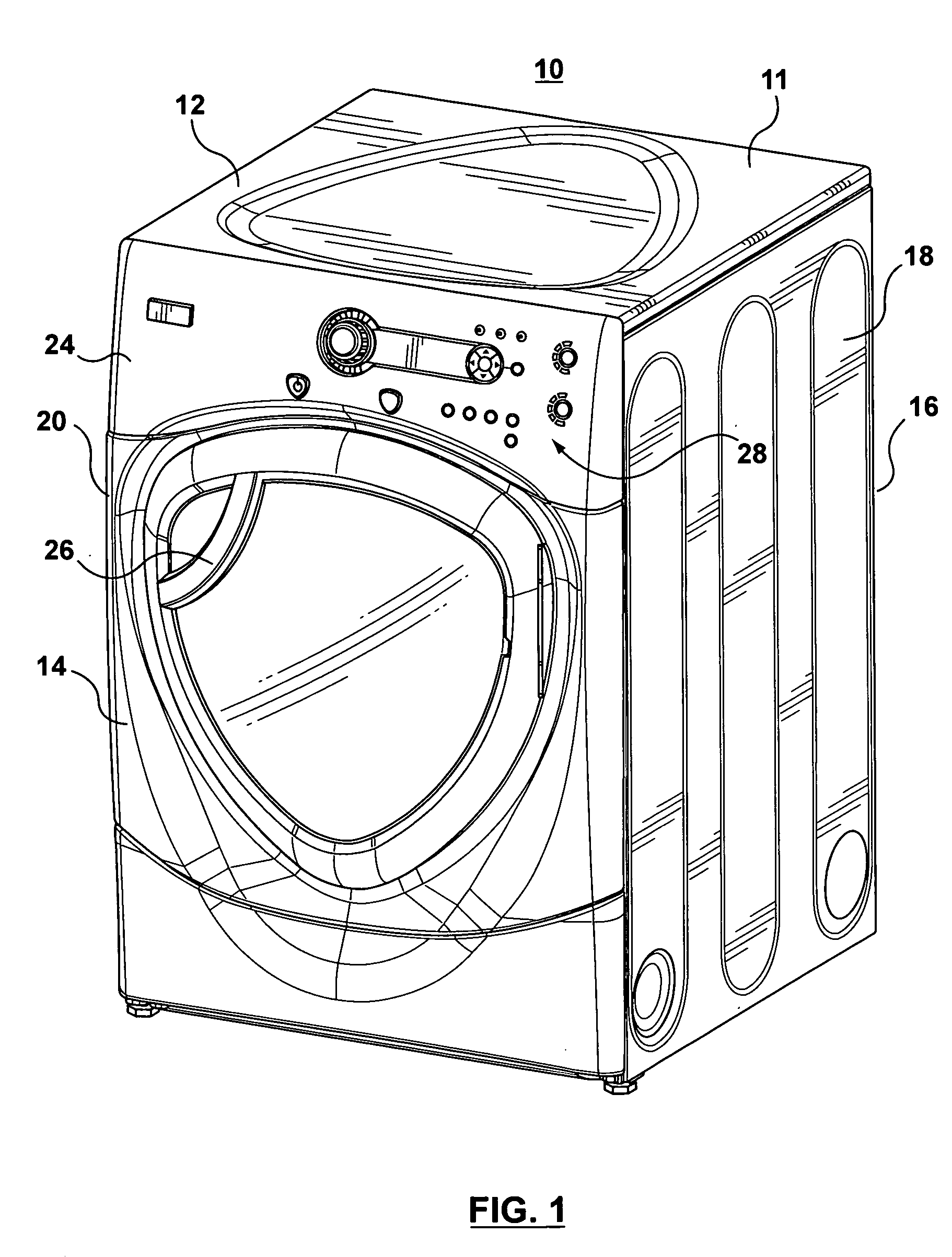
[0033]Referring to FIG. 1, there is shown a clothes dryer 10 comprising a cabinet 11. The cabinet has a top panel 12, a front wall 14, rear wall 16 and side walls 18, 20 and a floor panel (not shown). The clothes dryer 10 includes a control panel 24 where a user can input commands related to the functioning of the dryer 10 via controls 28. Although FIG. 1 shows an electronic control panel, other embodiments may include an analog control panel. The clothes dryer 10 further includes a door 26 which, when opened permits access to the rotating dryer drum (not shown) for the insertion and removal of clothing articles (not shown) therefrom. The clothes dryer 10 further includes four adjustable feet 17 located at the lower corners of the clothes dryer 10. These feet 17 together with rear dryer floor supports (not shown) support the clothes dryer 10 above a floor or ground of a room in which the dryer is operated.

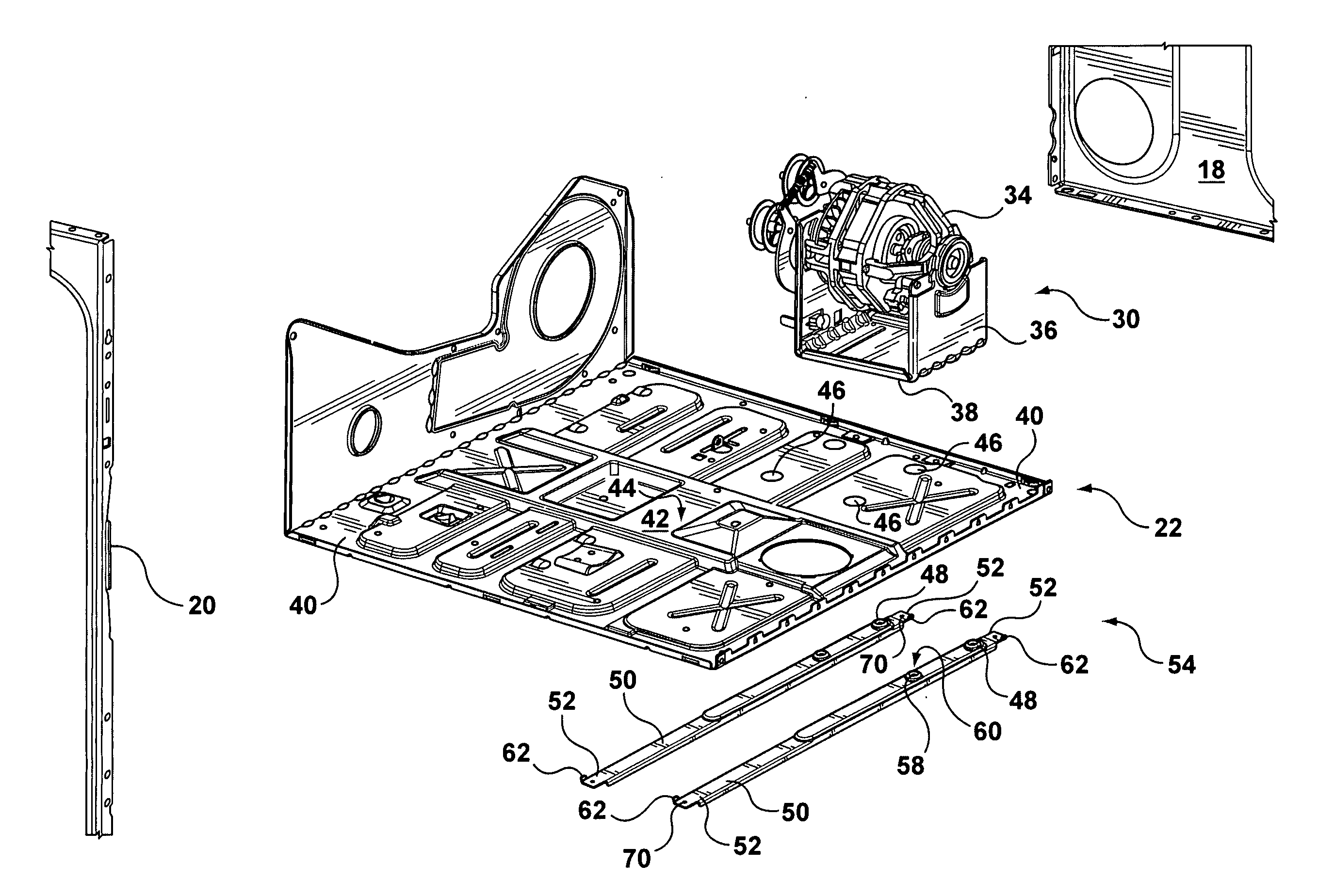
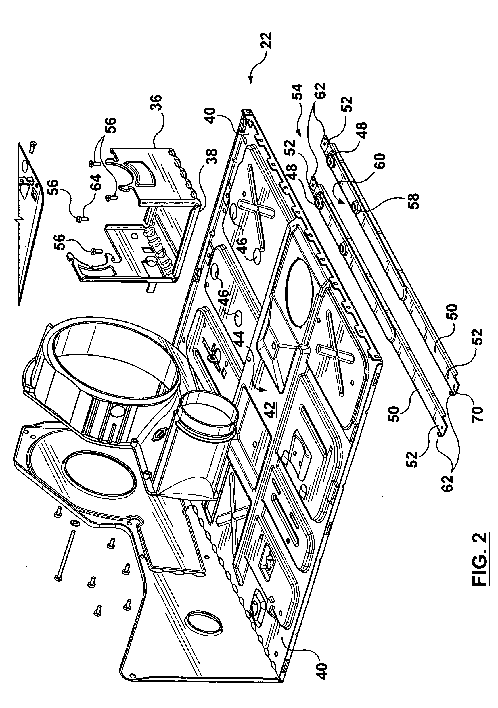
[0034]In FIGS. 2 and 3 the floor 22 of the cabinet 11 is shown in detail. The ...


PUM


Abstract

The present invention relates to a dryer motor assembly support that limits or eliminates cabinet vibration and noise. The dryer comprises a cabinet comprising a floor having an outside peripheral portion, and a central portion with four openings. The dryer further comprises a motor assembly, having a motor and motor mount comprising a base, spaced above the openings. A support assembly for supporting the motor assembly comprises two parallel spaced apart support portions each spaced below and spanning across the central portion, passing beneath the openings. Each support portion has oppositely disposed end portions secured with the peripheral portion. Each support portion comprises two projections extending therefrom toward the base. Each projection passes through a corresponding one of the openings with clearance to secure the support portion with the base, isolating the motor. The motor and support assembly, and the openings are co-located away from the central portion.

Description

FIELD OF THE INVENTION[0001]The present invention relates to a clothes dryer motor support assembly, more particularly, it relates to the support of the motor relative to the dryer cabinet.BACKGROUND OF THE INVENTION[0002]Clothes dryer motor assemblies typically comprise a motor mount having a motor mounted thereto. The motor mount may rest directly on a floor of the dryer cabinet or may rest atop a raised floor portion. In other prior assemblies, the motor is suspended from above by a raised platform.[0003]Clothes dryer motors produce a substantial amount of vibration which may be transmitted to the cabinet floor. This vibration produces noise as the cabinet vibrates. In some cases, the motor vibration may cause the dryer cabinet, or more specifically, the cabinet floor, to resonate. Resonance can generate loud unwanted noise. Vibration and noise are very displeasing to a user of the clothes dryer.[0004]In the past, clothes dryer apparatus have been developed to overcome the proble...

Claims


Application Information

Patent Timeline
Patent Type & Authority Applications(United States)
IPC IPC(8): F16M13/00D06F58/02
CPCD06F58/08D06F37/206
Inventor BRUNEAU, PIERRE-ANDREROY, JAMIELAROCHELLE, DOMINIQUE
Owner MABE CANADA
Why Eureka
Try Eureka