Combined vibration isolation device installed in transformer oil tank and design method

A technology for transformer oil tank and transformer, applied in the field of transformers, can solve the problems of ineffectiveness of vibration isolation measures, increasing magnetostriction of Guangxi steel sheets, and destroying material properties.

Pending Publication Date: 2020-02-18
绍兴建元电力集团有限公司 +1
View PDF0 Cites 6 Cited by
  • Summary
  • Abstract
  • Description
  • Claims
  • Application Information

AI Technical Summary

Problems solved by technology

[0005] 2. Improve the mechanical processing technology of silicon steel sheets of iron core. Silicon steel sheets are often severely impacted during production and processing, which will damage the material properties and increase the magnetostriction of Gui steel sheets, which will cause an increase in core noise.
Vibration isolation measures with a single frequency cannot achieve a good effect

Method used


Image

  • Combined vibration isolation device installed in transformer oil tank and design method
  • Combined vibration isolation device installed in transformer oil tank and design method
  • Combined vibration isolation device installed in transformer oil tank and design method

Examples


Embodiment 1

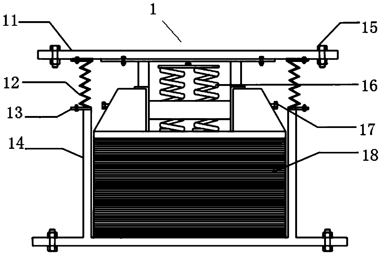
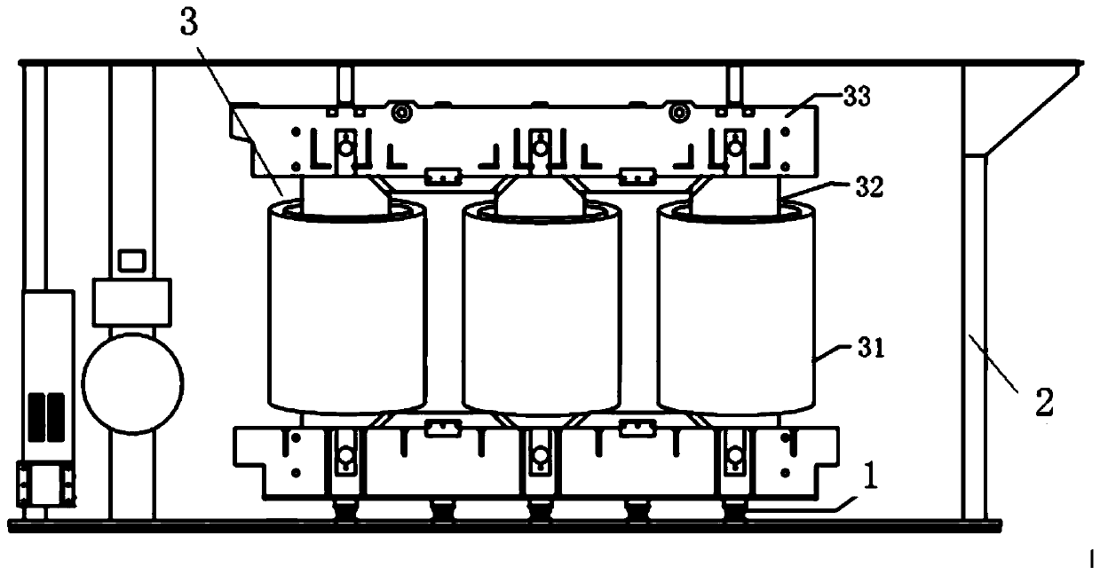
[0046] refer to figure 1 and figure 2 As shown, a vibration isolation and noise reduction device 1 for a transformer body is installed at the connection between the body 3 and the box inside the transformer oil tank 2 . The body 3 includes a base, a winding 31 , an iron core 32 , a clip 33 , etc. For specific structures, reference may be made to the prior art. This vibration isolation and noise reduction device 1 comprises a container 14 positioned at the bottom, a metal rubber vibration damping pad 18 installed in the container, a top cover 11 positioned above the container, and a flange 13 is connected to the periphery of the upper port of the container, so that A bellows 12 is connected between the flange 13 and the top cover 11, the upper edge of the bellows 12 is connected with a flange, and a damping spring vibration isolator is provided between the metal rubber damping pad 18 and the top cover 11. .

[0047]When the vibration isolation and noise reduction device is ...

Embodiment 2

[0053] A design method for a transformer body vibration isolation and noise reduction device installed inside a transformer oil tank.

[0054] Technical principle

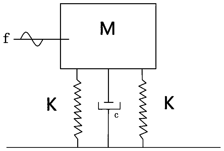
[0055] The general active vibration isolation model can be regarded as a single-degree-of-freedom vibration system with mass M, stiffness K, and viscoelastic damping coefficient c. Such as image 3 shown. Its vibration transmissibility is:

[0056]

[0057] In the formula: f is the vibration source frequency, f 0 is the natural frequency of the support system, and the damping ratio of the ξ vibration isolator.

[0058] The natural frequency of the support system is:

[0059]

[0060] In the formula: K is the stiffness of the vibration isolator, and m is the mass of the object.

[0061] Figure 4 is the vibration transmissibility curve, given by Figure 4 It can be seen that:

[0062] when f / f 0 = 1, the vibration transmission rate is the largest, and the system is in a dangerous resonance state at t...


PUM

PropertyMeasurementUnit
diameteraaaaaaaaaa
heightaaaaaaaaaa

Abstract

The invention discloses a combined vibration isolation device installed in a transformer oil tank and a design method. The device is installed at each of the joints of a transformer body in the transformer oil tank and a box body, and comprises a container, a metal rubber vibration isolation pad and a top cover, wherein the container is located at the lower portion, the metal rubber vibration isolation pad is installed in the container, and the top cover is arranged above the container; the periphery of an opening part of the upper end of each container is connected with a flange plate; corrugated pipes are connected between each flange plate and the corresponding top cover; and a damping spring vibration isolator is arranged between each metal rubber vibration isolation pad and the corresponding top cover. The combined vibration isolation device performs vibration isolation in allusion to different resonant frequencies of the transformer body in a manner of series connection combination of the metal rubber vibration isolation pads and the damping spring vibration isolators, and thereby, vibration transmission is weakened to the maximum degree, the vibration isolation bandwidth isincreased, and the goal of reducing the noise of the transformer is better achieved.

Description

technical field [0001] The invention belongs to the technical field of transformers, and in particular relates to the vibration and noise reduction technology of transformers. Background technique [0002] With the rapid development of urbanization in our country, substations go deep into the load center, and the distance between them and residents is getting closer and closer. The main noise sources of substations are transformers, reactors and other equipment. The vibration and noise of transformers and other equipment have become an important source of environmental noise and have attracted more and more attention. The radiation noise of the transformer is mainly caused by the vibration on the surface of the oil tank, and the vibration on the surface of the oil tank is caused by the vibration of the iron core and winding, that is, the vibration of the transformer body during operation. The vibration of the iron core and winding is transmitted to the oil tank through the c...

Claims


Application Information

Patent Timeline
Patent Type & Authority Applications(China)
IPC IPC(8): F16F15/08H01F27/33
CPCF16F15/085H01F27/33
Inventor 陶鸿飞黄剑莫国华曹枚根闵鹤群张宏王守康
Owner 绍兴建元电力集团有限公司
Why Eureka
Try Eureka