Load-compensation device

a load compensation and load technology, applied in mechanical control devices, hydraulic couplings, hydraulic equipment, etc., can solve the problems of wire breaking, deviation in the geometric relationship of various elements, and inability to fully compensate loads, etc., to achieve large degree of design freedom, wide range of weights, and large degree of freedom

Inactive Publication Date: 2012-07-26
KEIO UNIV
View PDF4 Cites 22 Cited by
  • Summary
  • Abstract
  • Description
  • Claims
  • Application Information

AI Technical Summary

Benefits of technology

[0023]The load compensation device according to the present invention has a structure whereby a load acting on a working arm is received by an actuator cylinder, and that load is transmitted to a spring member by way of a compensation cylinder which is linked to the actuator cylinder by a conduit, so there is no risk of an accident in which the working arm falls due to breakage caused by wear or fatigue of a wire, as in conventional load compensation devices employing a wire and a tension coil spring, it is possible to handle large loads, and a high level of safety and durability can be achieved.
[0024]The actuator cylinder and the compensation cylinder are linked by a conduit, so there is a large degree of freedom in the places where the compensation cylinder and spring member are positioned. Furthermore, by varying the pressure-receiving surface area ratio of the actuator cylinder and compensation cylinder, it is possible to select the tensile force produced by the piston rod of the actuator cylinder and the apparent spring constant during extension / contraction displacement in a range which is the square of the pressure-receiving surface area ratio, so there is a large degree of design freedom for the load compensation device and a broad range of weights can be handled.
[0025]In the load compensation device according to the present invention, it is possible to adopt a layout in which the actuator cylinder and the piston rod thereof are oriented in opposite directions, and the piston rod side is linked to the second pivot-mounting part and the actuator cylinder is linked to the third pivot-mounting part; if necessary, it is possible to select either of the two systems, so there is a large degree of design freedom.
[0026]With the load compensation device according to the present invention, the actuator cylinder or compensation cylinder used for compensating a load on the working arm may also be used as a drive mechanism for driving the working arm, so there is no need to provide a separate drive cylinder device etc., and the device can be made more compact and lightweight, while maintenance is simplified and production costs can be reduced.
[0027]With the load compensation device according to the present invention, a load which acts on the working arm is received by a compression coil spring by way of a guide rod, so there is no risk of an accident in which the working arm falls due to breakage caused by wear or fatigue of a wire, as in conventional load compensation devices employing a wire and a tension coil spring, and a high level of safety and durability can be achieved.
[0028]A load which acts on the working arm is received by the combined guide rod and compression coil spring, so heavier objects can be handled, compared with a conventional load compensation device employing a wire.

Problems solved by technology

However, with the load compensation device A1 described above, when the working arm A3 pivots up or down and the wire A4 supporting the working arm A3 passes between the pair of guide pulleys A5, A6 and bending is repeated over a long period of time, there is a risk of the wire breaking due to fatigue, which may lead to an accident in which the working arm A3 falls.
Furthermore, if the diameter of the wire A4 supporting the working arm A3 is increased, or the diameter of the guide pulleys A5, A6 for bending and guiding the wire A4 is increased, this produces a deviation in the geometric relationships of the various elements forming a device such as that described above for compensating load, and it is no longer possible to fully compensate loads, so such a device cannot readily be applied to a working arm on which large loads act.

Method used


Image

  • Load-compensation device
  • Load-compensation device
  • Load-compensation device

Examples


exemplary embodiment 1

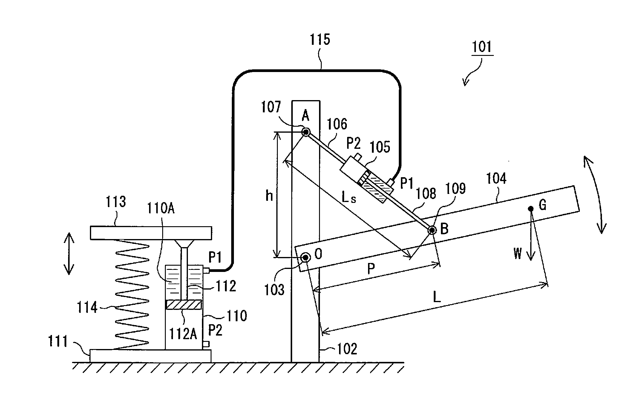
[0049]FIG. 1 is a schematic diagram of Exemplary Embodiment 1 of the load compensation device according to the present invention; in this figure, a load compensation device 101 comprises a supporting body 102 which is secured to a floor surface. A working arm 104 is supported on the supporting body 102 by means of a horizontal shaft 103 (first pivot-mounting part) in such a way as to be able to pivot about said shaft 103.

[0050]Furthermore, at a point A which is a position lying a distance h vertically above the center O of the shaft 103 of the supporting body 102, an actuator cylinder 105 is pivotably supported by a shaft 107 (second pivot-mounting part) parallel to the shaft 103, with the interposition of a linking rod 106 which is fixed to the head side of the actuator cylinder 105.

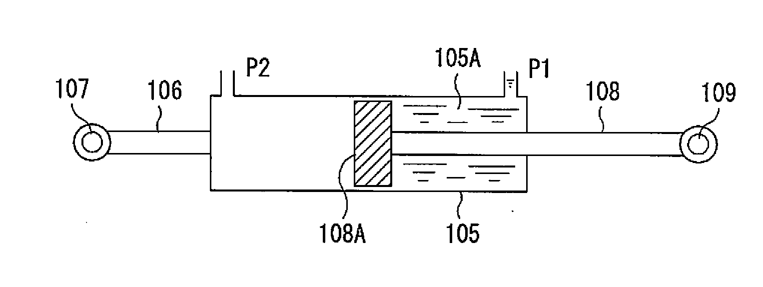
[0051]As shown in FIG. 2, a piston 108A provided at one end of a piston rod 108 is slidably inserted inside a cylinder chamber 105A of the actuator cylinder 105. Furthermore, ports P1 and P2 for providi...

exemplary embodiment 2

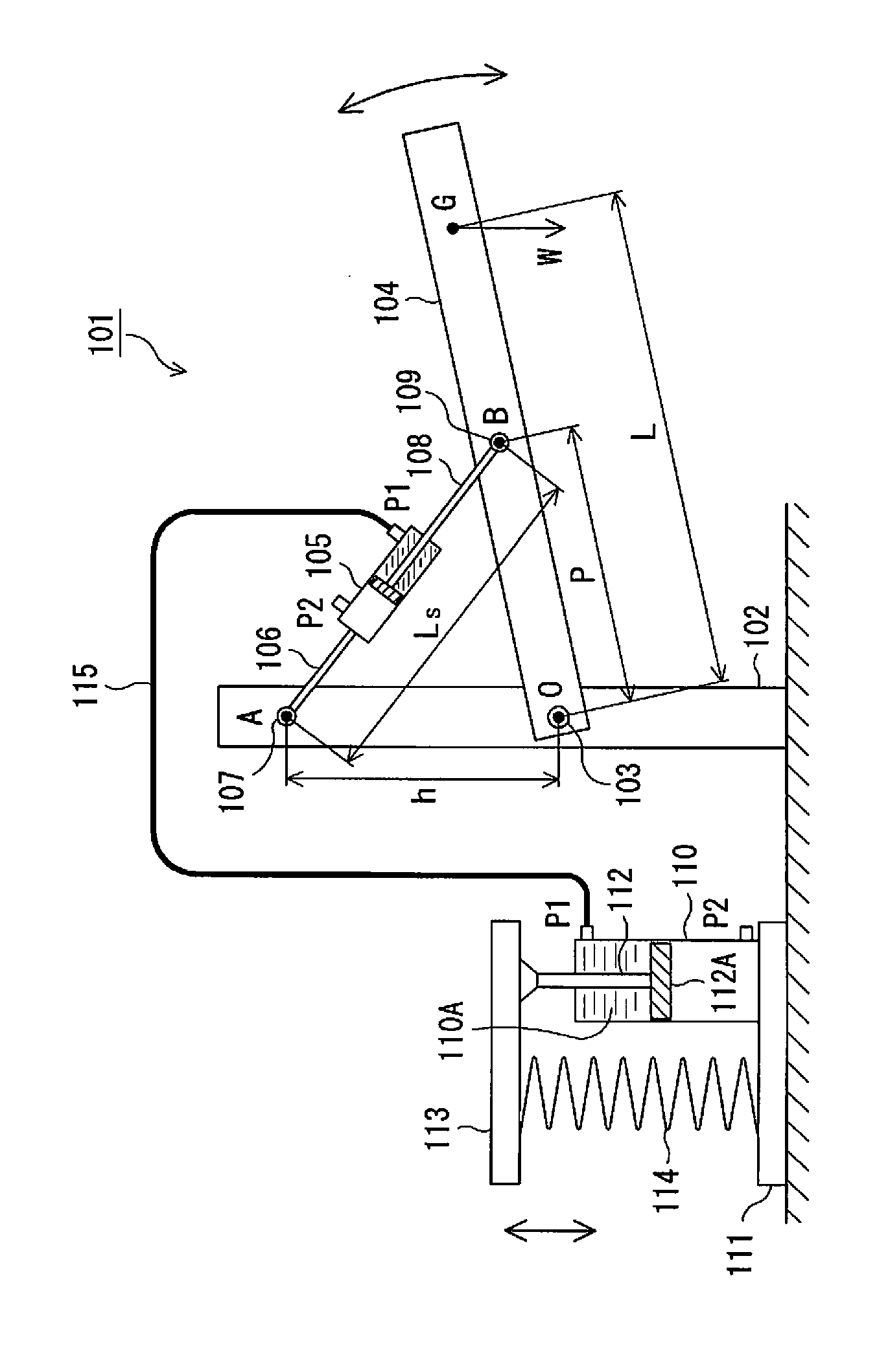
[0070]FIG. 3 is a schematic diagram of Exemplary Embodiment 2 of the load compensation device according to the present invention; in the load compensation device 101A shown in this figure, the outer peripheral surface at the end of an actuator cylinder 105′ on the piston rod 108′ side is pivotably supported on the supporting body 102 by a shaft 107′ (second pivot-mounting part), and elements in this figure having the same number as in FIG. 1 constitute substantially the same elements as in the load compensation device 101 described above.

[0071]The load compensation device 101A shown in FIG. 3 operates under the same load compensation principle as the load compensation device 101 described above, but the end position of the actuator cylinder 105′ on the rod side is rotatably supported on the supporting body 102 by the shaft 107′, and as a result it is possible to lengthen the stroke of the piston rod 108′, which has the advantage of increasing the range of pivoting of the working arm...

exemplary embodiment 3

[0072]In the load compensation device 1013 shown in FIG. 4, driving working fluid is supplied to the port P2 on the head side of the compensation cylinder 110 and the port P2 on the head side of the actuator cylinder 105′ in the load compensation device 101A described above, or a pair of driving conduits 116A, 116B for discharge are further added; the other elements have substantially the same configuration as in the load compensation device 101A shown in FIG. 3.

[0073]In the load compensation device 101B, the driving conduits 116A, 116B are connected to a driving fluid circuit which is not depicted. A known hydraulic circuit or the like comprising a hydraulic pump and a directional switching valve etc. is used as the driving fluid circuit, for example.

[0074]In the device in this exemplary embodiment, the piston 112A of the compensation cylinder 110 is pushed down when working fluid is supplied from one of the driving conduits 116A to the compensation cylinder 110 while the load torq...


PUM


Abstract

[Summary][Problem] To provide a load compensation device which can compensate loads on a working arm, and has excellent safety and durability.[Means of Resolution] A working arm 104 is supported by a first pivot-mounting part 103 on a supporting body 102, an actuator cylinder 105 is supported by a second pivot-mounting part 107 above the first pivot-mounting part 103, and a piston rod 108 of the actuator cylinder 105 is linked to a third pivot-mounting part 109 of the working arm 104. A piston rod 112 of a compensation cylinder 110 is linked to a movable frame 113, and a piston 112A of the compensation cylinder 110 is urged upward by means of a compression coil spring 114 which pushes the movable frame 113 upward. The actuator cylinder 105 and the compensation cylinder 110 are linked by the inside of a conduit 115, and when the working arm 104 is pivoted, the displacement of the piston of the actuator cylinder 105 urges the piston of the compensation cylinder 110, a torque which balances the load torque of a load W on the working arm 4 is generated, and a balanced state is maintained regardless of the angle of the working arm 104.

Description

TECHNICAL FIELD[0001]The present invention relates to a load compensation device for balancing a weight force acting on a working arm as a whole, in a robot provided with such a working arm, a manipulator or a working machine.PRIOR ART[0002]Conventional examples of load compensation devices such as a robot provided with a working arm which pivots within a vertical plane include a device in which a weight force acting on a working arm and a workpiece or the like held thereby is balanced with a spring force using a wire and a coil spring linked thereto, regardless of the angle of inclination of the working arm, as disclosed in Patent Documents 1 and 2.[0003]FIG. 16 is a schematic diagram of the structure of this kind of conventional load compensation device; a load compensation device A1 has a working arm A3 which is supported by a supporting body A2 placed on a horizontal floor surface, in such a way as to be able to pivot about a horizontal shaft at a point O, and one end of a wire ...

Claims


Application Information

Patent Timeline
Patent Type & Authority Applications(United States)
IPC IPC(8): B25J19/00B66F19/00
CPCB25J19/0012Y10T74/20305B66C23/005B25J19/0016F15B7/02
Inventor YAMADA, YASUYUKIMORITA, TOSHIO
Owner KEIO UNIV
Why Eureka
Try Eureka