Supercharge Your Innovation With Domain-Expert AI Agents!

Aircraft engine fuel system

a fuel system and engine technology, applied in the direction of machines/engines, positive displacement liquid engines, separation processes, etc., can solve the problems of fuel heating, engine fuel consumption increase, fuel rejection in the conventional system described briefly above,

Active Publication Date: 2012-07-26
HAMILTON SUNDSTRAND CORP
View PDF2 Cites 3 Cited by
  • Summary
  • Abstract
  • Description
  • Claims
  • Application Information

AI Technical Summary

Problems solved by technology

Thus, there will be many operating conditions, notably engine idle conditions where the output of the pump exceeds the demand of the engine.
The conventional system described briefly above often suffers from “heat rejection”.
When the gear pump is pumping fuel against system pressure, the action of spilling fuel in excess of engine demand to the low pressure side of the system results in fuel heating.
In addition, energy from the engine is wasted in heating the fuel through heat rejection at the fuel pumps thus resulting in an overall increase in engine fuel consumption.

Method used


Image

  • Aircraft engine fuel system
  • Aircraft engine fuel system
  • Aircraft engine fuel system

Examples


Embodiment Construction

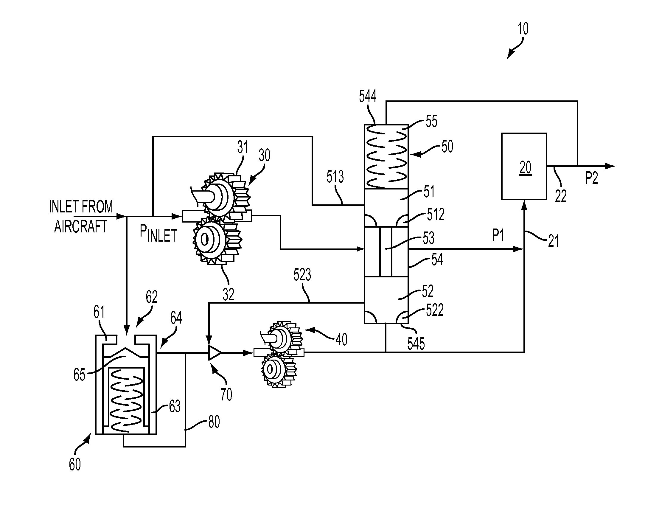
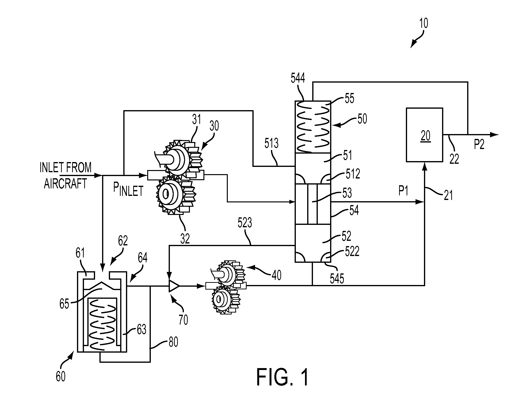
[0014]The proposed pump unloading valve eliminates disturbances in the metered flow during the pump unloading sequence, which occur in similar systems in which the auxiliary pump is unloaded via a check valve to the low pressure fuel supply. In these cases, the ability of the additional fuel volume to be compressed causes an unacceptable disturbance in the metered flow and pressure. The proposed unloading valve, however, maintains a relatively constant pressurized fuel volume of fuel as the auxiliary pump is unloaded. This results in a more accurate control of delivered metered flow.

[0015]With reference to FIGS. 1-3, an aircraft engine fuel system 10 is provided and includes a metering valve 20. The system 10 provides pump unloading and pressure regulation across the metering valve 20 from an inlet side 21 thereof at pressure P1 to an outlet side 22 thereof at pressure P2 while limiting fuel flow disturbances to metered fuel flow during pump unloading.

[0016]The system 10 further inc...


PUM

PropertyMeasurementUnit
pressureaaaaaaaaaa
rotational speedaaaaaaaaaa
shaft speedaaaaaaaaaa

Abstract

An aircraft fuel system is provided and includes a metering valve having inlet and outlet sides to monitor fuel flow from the inlet to the outlet side, a check valve that, when opened, allows fuel to flow toward the inlet side during start and climb conditions and, when closed, prevents such fuel flow and an ejector pump, which is operably disposed between the check valve and the metering valve, and which, with the check valve closed, pumps fuel toward the inlet side during idle conditions.

Description

BACKGROUND OF THE INVENTION[0001]The subject matter disclosed herein relates to an aircraft engine fuel system and, more particularly, to an aircraft engine fuel system including a pump unloading valve.[0002]A conventional fuel supply system uses a positive displacement pump, for example a gear pump, which is driven by an engine through an accessory gearbox, to provide fuel through a fuel metering system to the burners of the engine. The positive displacement pump which, in the interests of clarity will be referred to herein as a “gear pump”, receives fuel from a fuel supply and has a rotational speed directly proportional to the shaft speed of the engine. Generally, the capacity and therefore the size of the pump is calculated on the basis of the maximum fuel flow which will be needed in use and a safety margin is applied on top of that maximum. Thus, there will be many operating conditions, notably engine idle conditions where the output of the pump exceeds the demand of the engin...

Claims


Application Information

Patent Timeline
Patent Type & Authority Applications(United States)
IPC IPC(8): F04B49/035
CPCF02C7/22F05D2260/604F05D2260/601F02C7/236F02C7/232Y10T137/86019
Inventor HEITZ, STEVEN A.
Owner HAMILTON SUNDSTRAND CORP
Features
  • R&D
  • Intellectual Property
  • Life Sciences
  • Materials
  • Tech Scout
  • Unparalleled Data Quality
  • Higher Quality Content
  • 60% Fewer Hallucinations
Learn More