Aircraft fuel supply systems

A fuel supply system, fuel system technology, applied in the direction of charging system, turbine/propulsion fuel delivery system, power plant fuel supply, etc., can solve problems such as fuel interruption or significant restriction, engine power loss, engine failure, etc.

Active Publication Date: 2015-02-11
伊顿智能电源有限公司
View PDF6 Cites 9 Cited by
  • Summary
  • Abstract
  • Description
  • Claims
  • Application Information

AI Technical Summary

Problems solved by technology

This will cause fuel vapor to gradually form while dissolved air comes out of solution, and if the ratio of gas and/or vapor to liquid fuel at the pump's inlet

Method used


Image

  • Aircraft fuel supply systems
  • Aircraft fuel supply systems

Examples


Embodiment Construction

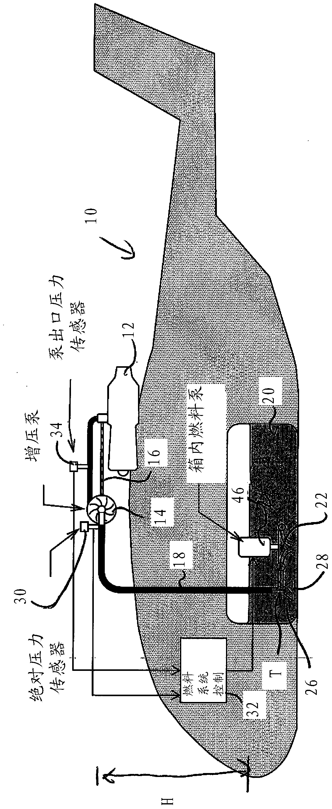
[0037] First refer to figure 1 , the illustrated helicopter 10 includes a power plant 12 to drive a rotor (not shown). The powerplant 12 is mounted on the upper portion of the helicopter fuselage and receives fuel from a main (downstream) fuel pump 14 which in this embodiment is driven by a power take-off shaft 16 from the powerplant 12 . Fuel is supplied to the main fuel pump 14 through a fuel line 18 extending from a fuel tank 20 located in the lower fuselage of the helicopter. It should be noted that there is a distinct oil level "H" between the pump and the fuel tank. As the size of the helicopter increases, so does this oil level, which means that the suction force required to overcome this oil level to get the fuel to the engine also increases. An upstream (supply) pump 22 is arranged in the fuel tank and is connected to the fuel supply line with a T-joint 24 . The other branch of the T-joint goes to the suction inlet 26 which includes a check valve 28 through which ...


PUM


Abstract

A fuel supply system for an aircraft 10 for delivering fuel from a fuel tank 20 to an aircraft power plant 12. The fuel supply system comprises a fuel flow passage 18 along which fuel flows from the tank to the power plant. The fuel flow passage has a downstream end adjacent the power plant and an upstream end adjacent the fuel tank. A downstream pump 14 is associated with the power plant for drawing fluid along the passage to supply it to the power plant. An upstream pump 22 is associated with the fuel tank and is operable to pump fluid along the passage. A pressure sensor 30 for monitoring the inlet pressure to the downstream pump, and a fuel system controller 32 are provided; the fuel system controller is responsive to the pressure sensor and controls the upstream pump to maintain the pressure at the inlet to the downstream pump at a predetermined threshold pressure.

Description

[0001] related application [0002] This invention was made with Government support under Contract No. N00019-06-C-0081 awarded by the Department of the Navy (Naval Air Systems Command). The government has certain rights in this invention. technical field [0003] The present invention relates to aircraft fuel supply systems and related methods for supplying fuel from fuel tanks to aircraft powerplants, and in particular, but not exclusively, to helicopter fuel supply systems. Background technique [0004] In a typical helicopter design, the fuel tank is located in the lower part of the helicopter, and the main power plant that drives the helicopter's rotor is located in the upper part of the helicopter. Fuel is drawn from the fuel tank through the fuel line by means of a suction pump located near the main power unit. Due to the reduced fire hazard when the fuel line between the tank and the pump is damaged, this suction configuration is preferred as the pressure differen...

Claims


Application Information

Patent Timeline
IPC IPC(8): B64D37/00B64C27/04
CPCB64C27/04F02C7/236B64D37/22F02C9/28Y10T137/0379F02M37/18F02M37/20F02M2037/085Y02T50/40B64D37/00F02C7/22B64C37/00B64D37/32B64D27/04
Inventor J·H·伍德
Owner 伊顿智能电源有限公司
Why Eureka
Try Eureka