Aircraft fuel system and aircraft

Active Publication Date: 2015-02-05
MITSUBISHI AIRCRAFT
View PDF10 Cites 10 Cited by
  • Summary
  • Abstract
  • Description
  • Claims
  • Application Information

AI Technical Summary

Benefits of technology

[0033]According to the present invention, it is possible to ensure explosion-proof performance wi

Problems solved by technology

Increasing the NEA supply capacity to avoid this situation requires a larger amount of bleed

Method used


Image

  • Aircraft fuel system and aircraft
  • Aircraft fuel system and aircraft
  • Aircraft fuel system and aircraft

Examples


Embodiment Construction

[0041]In the following, embodiments of the present invention will be described with reference to the accompanying drawings.

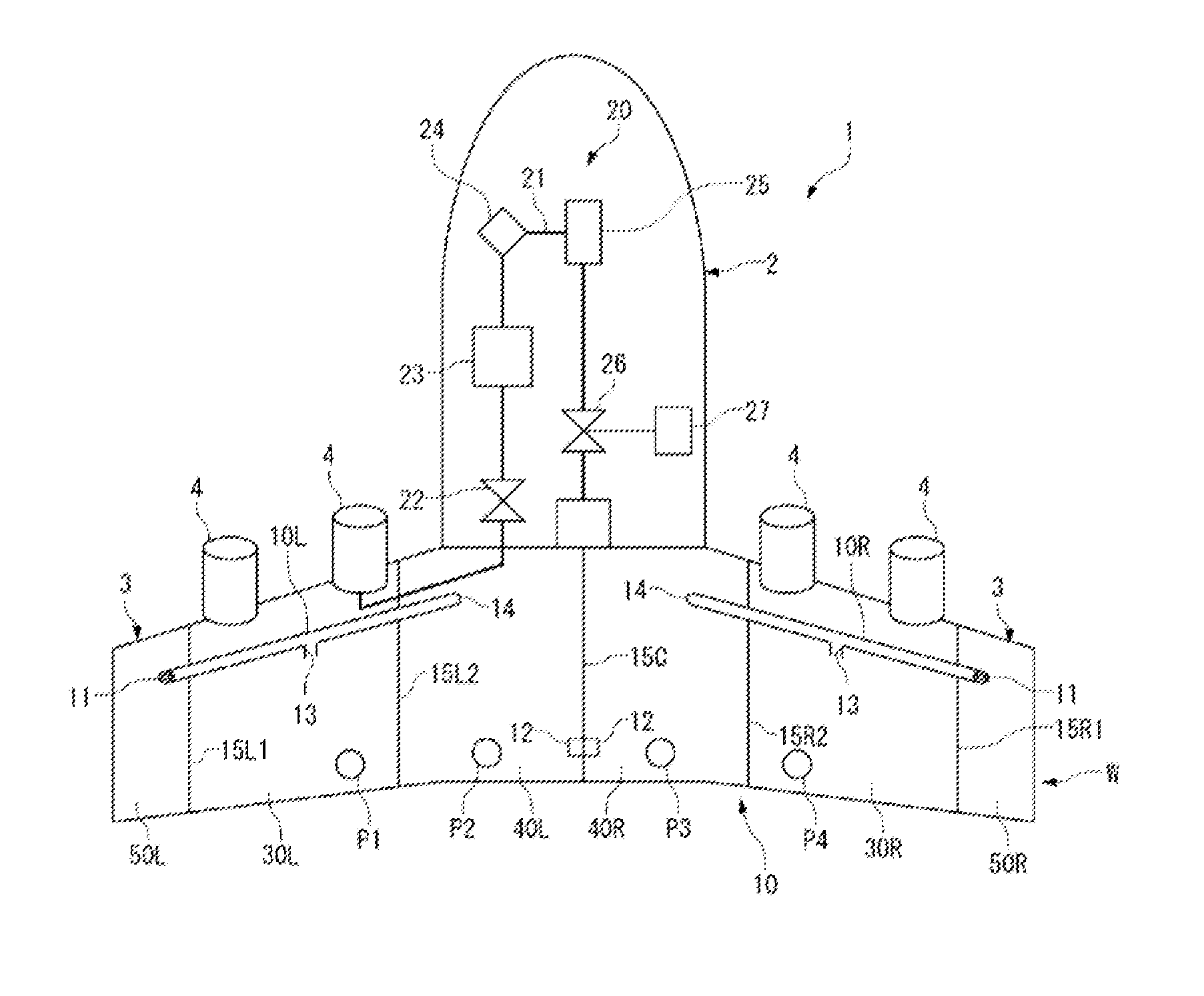
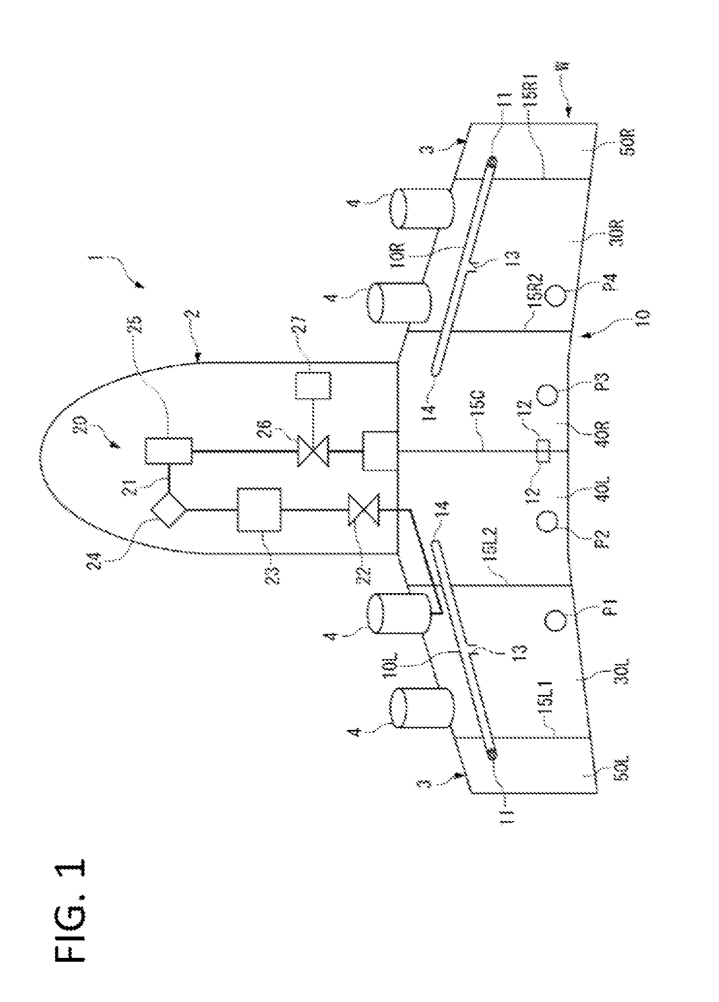
[0042]A fuel system 10 having multiple fuel tanks is installed in an aircraft 1 shown in FIG. 1. For preventing explosion, the fuel system 10 has an NEA supply system 20 which supplies the fuel tanks with nitrogen-enriched air (NEA) which is richer in nitrogen relative to the air.

[0043]First, the basic structure of the aircraft 1 will be described.

[0044]The aircraft 1 includes a fuselage 2, and a pair of main wings 3 and 3 extending to the left and the right from the fuselage 2.

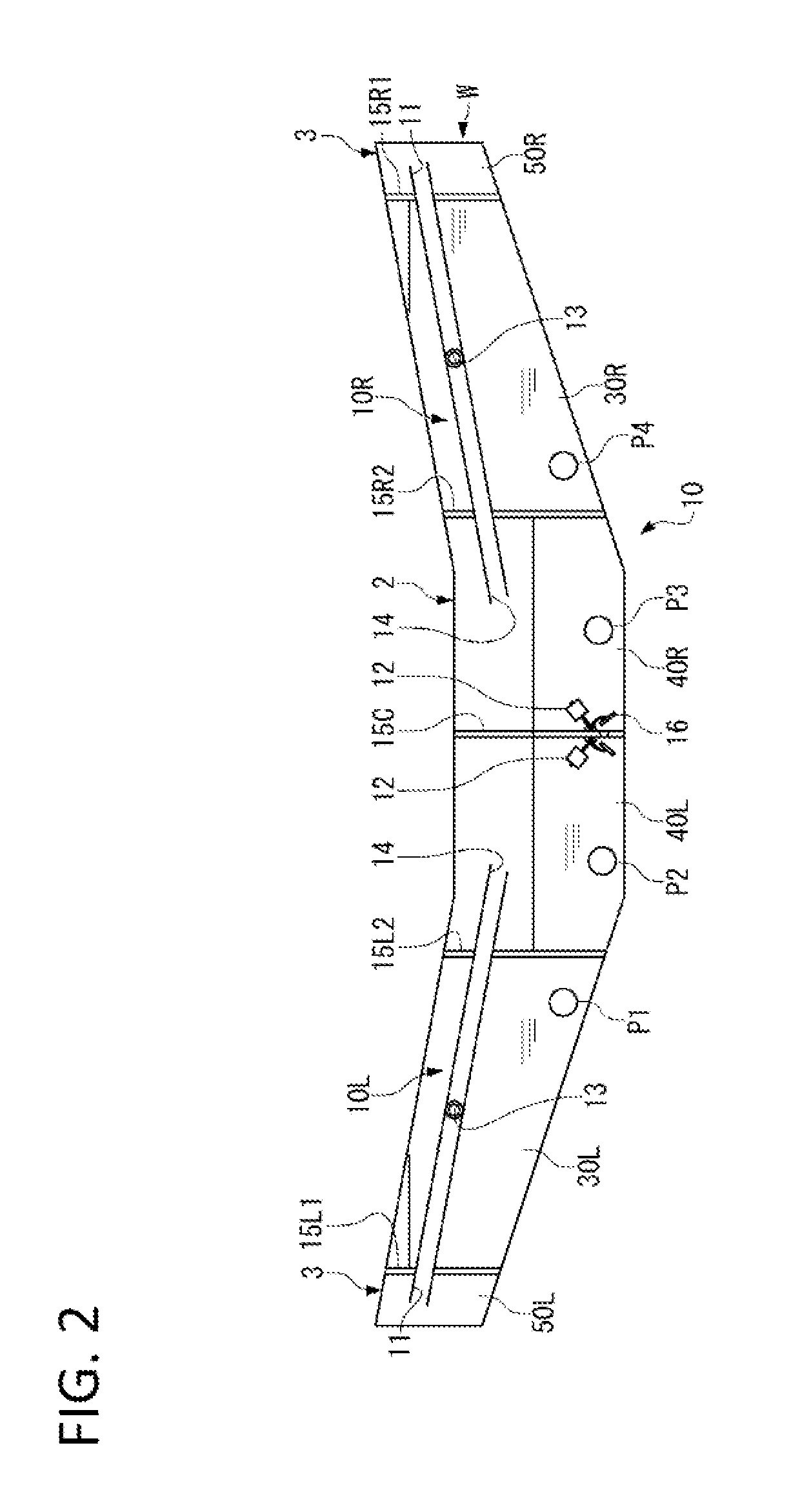
[0045]The main wing 3 includes spars, skins, stringers, and ribs. These spars, skins, stringers, and ribs are assembled to form a wing box W. The wing box W extends along almost the entire main wings 3 and 3 in their length direction and across the fuselage 2.

[0046]Next, the configuration of the fuel system 10 will be described with reference to FIG. 1 and FIG. 2.

[0047]The fuel system 10 ...


PUM


Abstract

The present invention ensures explosion-proof performance without increasing the capacity for supplying nitrogen-enriched air in an aircraft fuel system having a ventilation function. An aircraft fuel system includes: fuel tanks; an NEA supply system; a left ventilation channel extending from a ventilation duct to a fuselage and leading into the tanks; and a right ventilation channel extending from a ventilation duct to the fuselage and leading into the tanks. The tank leading to the channel and the tank leading to the channel are separated by a central wall. The tanks communicate with each other through a fuel path, which allows, of fuel and gas, only the fuel to pass through, and float valves.

Description

BACKGROUND OF THE INVENTION[0001]1. Field of the Invention[0002]The present invention relates to an aircraft fuel system equipped with a fuel tank to which nitrogen-enriched air richer in nitrogen than the air is supplied.[0003]2. Description of the Related Art[0004]In a flying aircraft, as the fuel tank is filled with vaporized fuel, it is necessary to prevent the fuel tank from exploding in events such as lightning strikes on the tank or wiring short-circuit. In this connection, an explosion-proof system has been proposed (U.S. Pat. No. 6,547,188). This system supplies the fuel tank with nitrogen-enriched air (hereinafter, NEA), which is higher in nitrogen concentration and lower in oxygen concentration than the air, with bleed air from the engine serving as a gas source.[0005]The outside air pressure changes during ascent and descent of an aircraft. During that time, it is necessary to avoid the fuel tank being subjected to an excessive pressure due to the differential pressure b...

Claims


Application Information

Patent Timeline
IPC IPC(8): B64D37/32B64D37/06B64D37/04
CPCB64D37/32B64D37/06B64D37/04
Inventor HASHIMOTO, JUNICHIROKOMODA, USHIO
Owner MITSUBISHI AIRCRAFT
Why Eureka
Try Eureka