Heat Sink Mount and Assembly

a heat sink and mounting plate technology, applied in the direction of basic electric elements, lighting and heating apparatus, semiconductor devices, etc., can solve the problems of plastic spring elements and plastic frames that experience plastic creep deformation, failure of conventional heat sink assemblies and mounts,

Active Publication Date: 2012-07-26
AAVID THERMALLOY LLV
View PDF4 Cites 46 Cited by
  • Summary
  • Abstract
  • Description
  • Claims
  • Application Information

AI Technical Summary

Benefits of technology

[0005]The heat sink mount and assembly is particularly suited for use with a ball grid array package. As used herein, “ball grid array package”, refers to a mounting configuration for an integrated circuit (IC), chip or microprocessor wherein the IC, chip or microprocessor is connected to a substrate having an array of solder balls on a reverse side of the substrate. The ball grid array package is joined to a printed circuit board (PCB) via the array of solder balls which, during solder re-flow or other soldering process, are melted to form both electrical interconnect of the BGA package to the PCB and to mechanically fix the BGA package to the PCB. After the solder reflow or other soldering process, a finite spacing or gap remains between the BGA package and t...

Problems solved by technology

A drawback of such existing heat sink assemblies is that the plastic spring element and the plastic frame experience plastic creep deformation caused by the force applied by the spring to the heat sink and by the heat tra...

Method used


Image

  • Heat Sink Mount and Assembly
  • Heat Sink Mount and Assembly
  • Heat Sink Mount and Assembly

Examples


Embodiment Construction

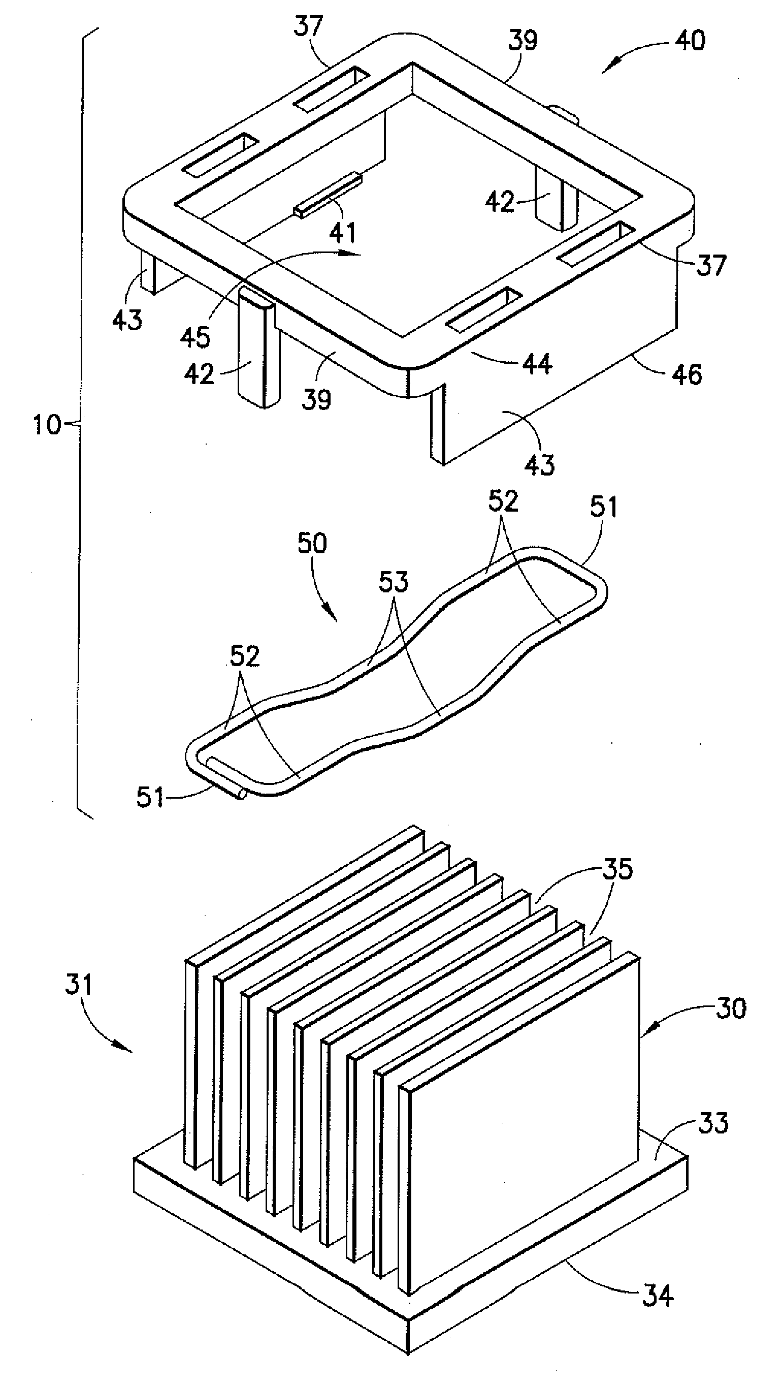
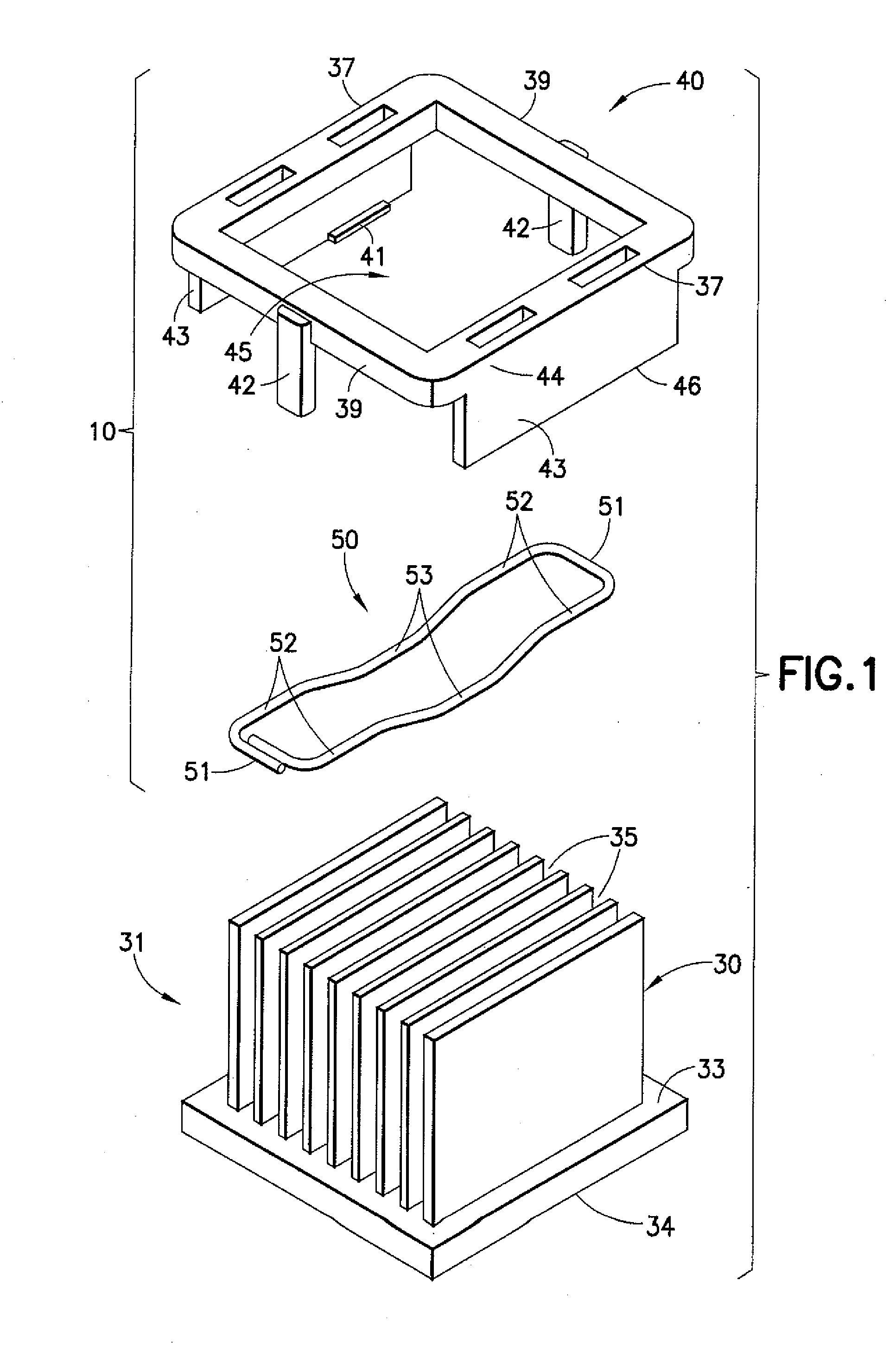
[0023]FIG. 1 is an exploded perspective view of an example embodiment of a heat sink mount 10 for a heat sink 31 in accordance with the present invention. The mount 10 includes a retaining device or clip 40 and a metal spring 50 for mounting heat sink 31 to a heat generating device, heat source, or thermal interface material and, in particular, to a heat generating device, heat source, microprocessor or integrated circuit (IC).

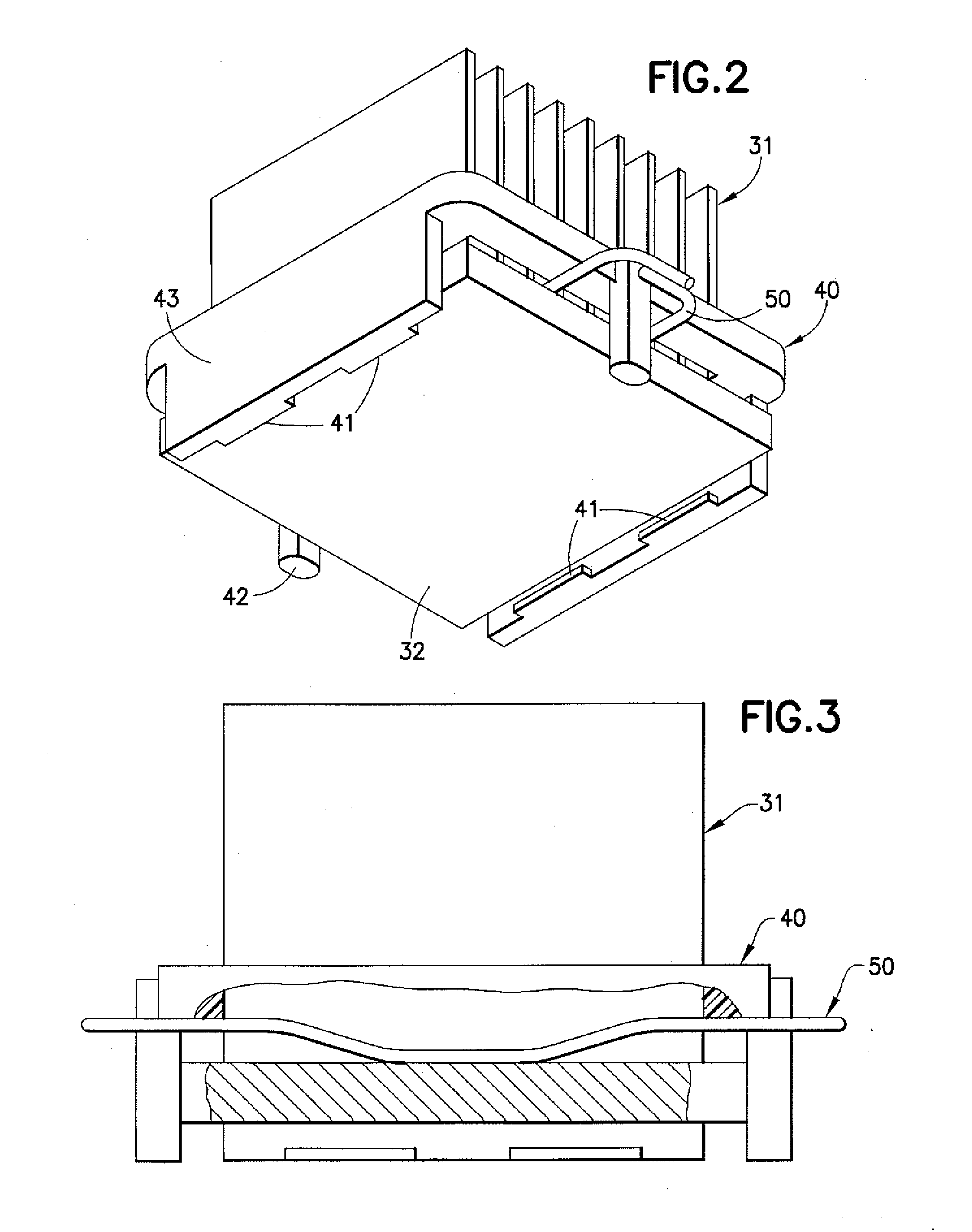
[0024]Referring to FIGS. 1-4, 4A, 4B, 5 and 6 the heat sink 31 comprises a base, namely, a contact plate 34 having opposed first and second faces 33, 32 and a plurality of spaced-apart fins 30 separated by gaps 35. The first face 33 of the heat sink 31 is engaged by the metal spring 50 between some of the fins 30 at gaps 35 when the heat sink 31 is coupled to the heat sink mount 10 as explained below. The second face 32 of the heat sink 31 is configured to engage the heat generating device or thermal interface material. The heat sink 31 may comprise aluminum, ...


PUM


Abstract

An assembly for a heat sink having a contact plate with opposing first and second faces, a plurality of fins extending from the first face of the contact plate, and a plurality of gaps between the fins. A retaining device has a first pair of opposing sides and a second pair of opposing sides, the first and second pairs of opposing sides surrounding an opening, the first pair of opposing sides having primary framing members, at least some of the primary framing members having a first end at a respective side and a distal free end, with at least one engagement member positioned proximate the distal free ends. The primary framing members define a receiving space for the heat sink. A metal spring is configured in a closed shape cross-section for engagement with the retaining device. The metal spring has a pair of elongated sides, a pair of truncated sides and heat sink engagement regions. The heat sink engagement regions are positioned against the contact plate when the metal spring is engaged with the retaining device, to urge the contact plate towards the engagement members. The assembly is particularly well suited for use with ball grid array packages to interface electronic components in such packages with the heat sink.

Description

FIELD OF THE INVENTION[0001]The present invention relates to a heat sink mount and in particular to a heat sink assembly that utilizes a spring element and retaining device for mounting a heat sink to a heat generating device.DESCRIPTION OF THE RELATED ART[0002]Conventional heat sink assemblies and mounts use a plastic spring element that is integrally formed with a plastic frame to create a contact force between a heat sink and a heat generating device. In particular, the plastic frame comprises a first opposing pair of sides and a second opposing pair of sides which surround an opening for receiving fins of the heat sink. The plastic spring applies a force to the heat sink to urge the heat sink in thermal contact with a heat generating device, such as an integrated chip (IC).[0003]A drawback of such existing heat sink assemblies is that the plastic spring element and the plastic frame experience plastic creep deformation caused by the force applied by the spring to the heat sink a...

Claims


Application Information

Patent Timeline
IPC IPC(8): F28F9/00
CPCH01L23/4093H01L2924/0002H01L2924/00F28D2021/0029F28F2280/06
Inventor TAN, RUI SHENGZHANG, XIONGLIU, ZHE HONGZHENG, SAN XI
Owner AAVID THERMALLOY LLV
Why Eureka
Try Eureka