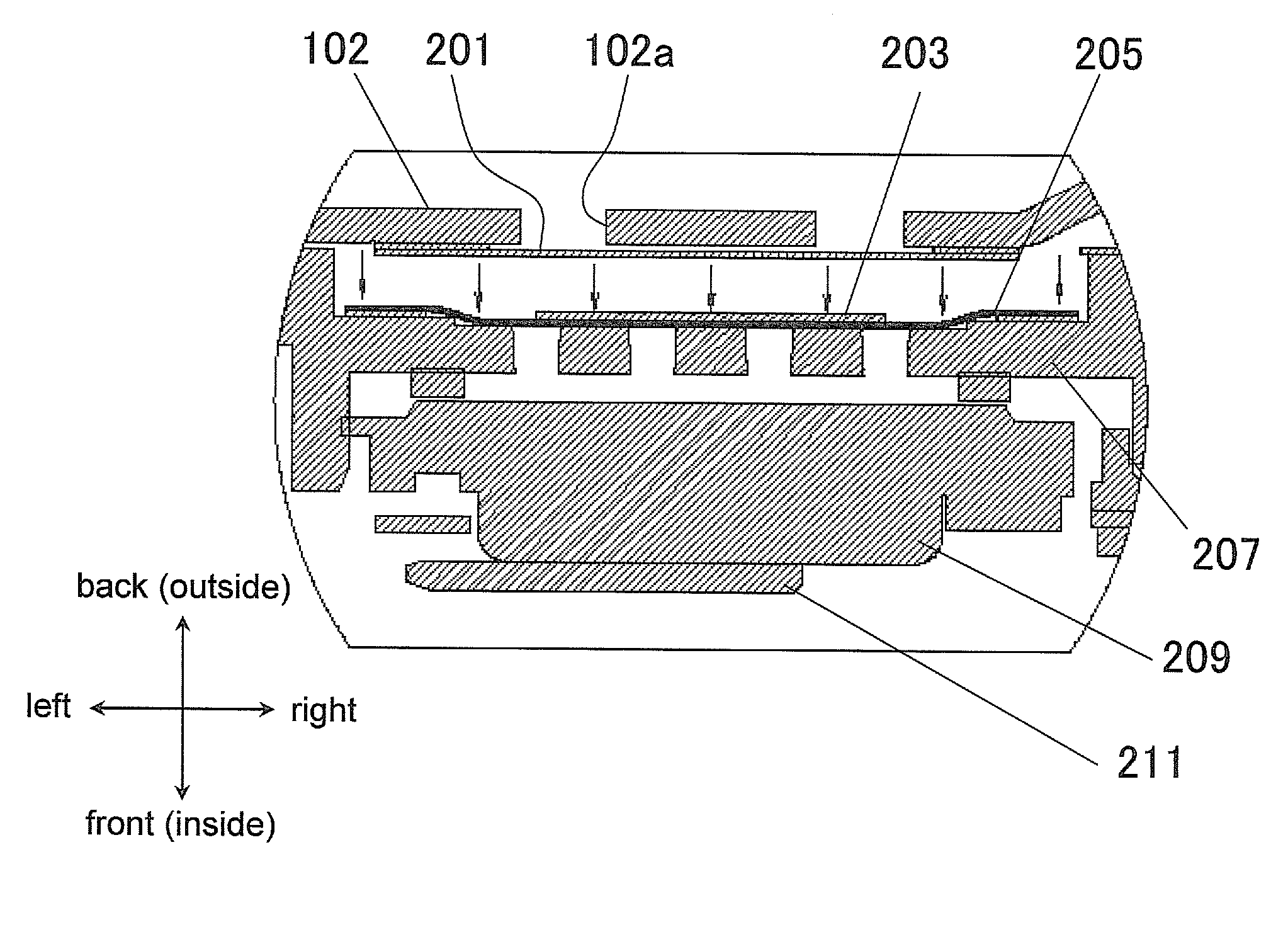
Waterproof structure for electronic device
a technology of electronic devices and structures, applied in the direction of television systems, electric apparatus casings/cabinets/drawers, instruments, etc., can solve the problems of secondary diaphragm deformation, noise generation, and difficulty in ensuring good sound pressure, so as to reduce rattling noise and good sound pressure
- Summary
- Abstract
- Description
- Claims
- Application Information
AI Technical Summary
Benefits of technology
Problems solved by technology
Method used
Image

Examples
Embodiment Construction
[0022]Selected embodiments will now be explained with reference to the drawings. It will be apparent to those skilled in the art from this disclosure that the following descriptions of the embodiments are provided for illustration only and not for the purpose of limiting the invention as defined by the appended claims and their equivalents.
[0023]These drawings, however, are merely schematic representations, and the various dimensional proportions and so forth may be different in reality. Therefore, the specific dimensions and so forth should be determined by referring to the following description. Also, it should go without saying that the dimensional relations and proportions may vary from one drawing to another.
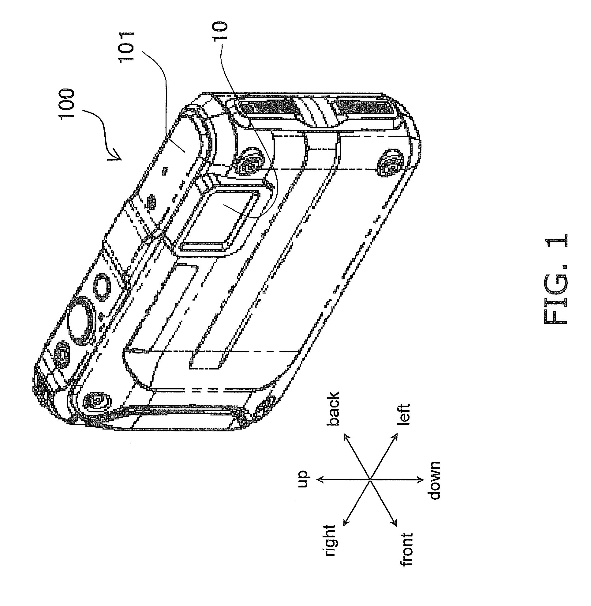
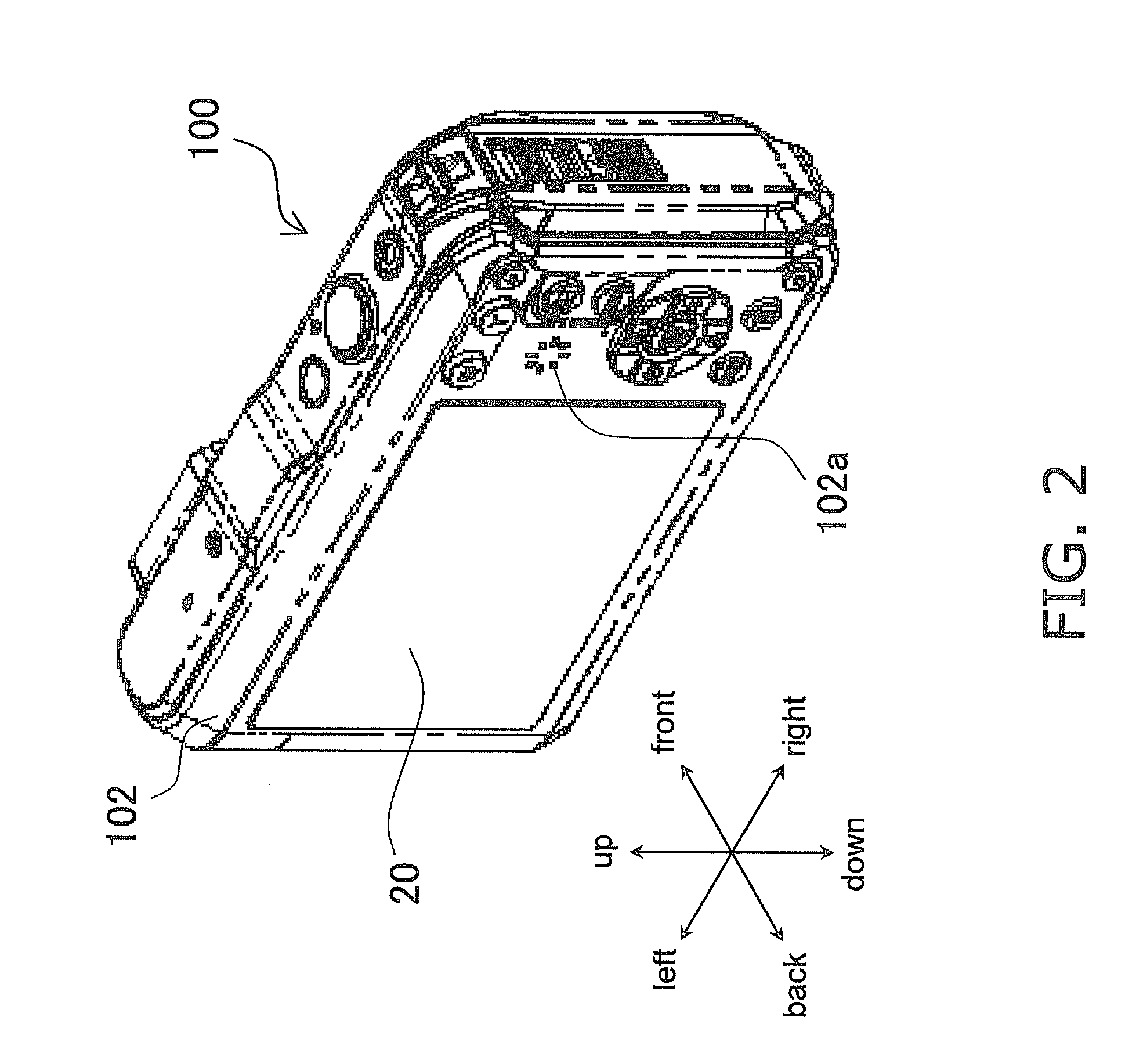
[0024]In the following embodiments, a digital camera will be used as one example of an electronic device equipped with a waterproof structure. In the following description, the direction facing the subject is defined as “forward,” the direction moving away from the subject ...
PUM
 Abstract
Description
Claims
Application Information
 - R&D
- Intellectual Property
- Life Sciences
- Materials
- Tech Scout
- Unparalleled Data Quality
- Higher Quality Content
- 60% Fewer Hallucinations
Browse by: Latest US Patents, China's latest patents, Technical Efficacy Thesaurus, Application Domain, Technology Topic, Popular Technical Reports.
© 2025 PatSnap. All rights reserved.Legal|Privacy policy|Modern Slavery Act Transparency Statement|Sitemap|About US| Contact US: help@patsnap.com