Unlock instant, AI-driven research and patent intelligence for your innovation.

Terminal block, method of manufacturing it and nut

a technology of terminal blocks and nut ends, which is applied in the direction of nuts, threaded fasteners, mechanical devices, etc., can solve the problems of small clearances, electrical devices generally generate heat, and conductors become hot, so as to reduce contact area, improve heat radiation performance of busbars and terminal blocks, and increase contact pressure of resin cut-off parts on steps.

Active Publication Date: 2012-07-26
SUMITOMO WIRING SYST LTD
View PDF7 Cites 19 Cited by
  • Summary
  • Abstract
  • Description
  • Claims
  • Application Information

AI Technical Summary

Benefits of technology

The invention is a terminal block that includes a nut with a fastening surface and a step at an outer periphery of the fastening surface. The step is recessed from the fastening surface and a molded resin is used to engage the step and prevent the nut from being pulled towards a bolt that engages the nut. The molded resin also covers the restricted surface of the step, improving heat transfer performance. The invention also includes a method of manufacturing the terminal block. The technical effects of the invention include improved heat transfer performance and a simplified manufacturing process.

Problems solved by technology

The electrical devices generally generate heat and the conductors become hot.
However, small clearances may be formed at parts of boundaries between the resin cut-off parts and the fastening surfaces.
This absence of direct contact reduces heat-transfer efficiency and heat radiation performance of the terminal block.
However, higher pressing forces may fracture the insulating member or damage the fastening surfaces to reduce contact areas with the busbars.

Method used


Image

  • Terminal block, method of manufacturing it and nut
  • Terminal block, method of manufacturing it and nut
  • Terminal block, method of manufacturing it and nut

Examples


Embodiment Construction

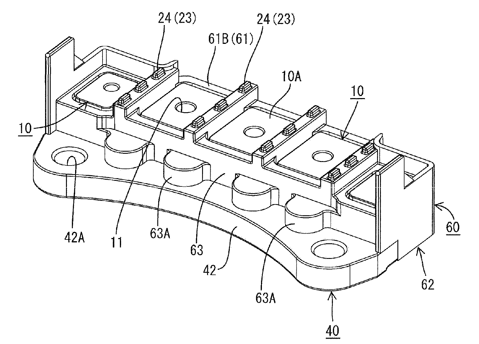
[0046]A terminal block in accordance with the invention is mounted in a motor case to be installed in a vehicle, such as an electric vehicle or a hybrid vehicle, and is provided to electrically connect a busbar of a first electric equipment, such as an electric motor (e.g. a three-pole busbar provided in a three-phase alternating current motor) and a busbar of a second electric equipment such as an inverter (e.g. a three-pole busbar provided in an inverter).

[0047]The terminal block includes nuts 10, each of which upper and lower surfaces. Unillustrated busbars extending from electrical devices are to be placed on the upper surfaces of the nuts 10. An insulating plate 20 is placed on the lower surface of the nut 10. A heat sink 40 is arranged adjacent a surface of the insulating plate 20 opposite the nuts 10. Thus, the insulating plate 20 is sandwiched vertically between the nuts 10 and the heat sink 40. Synthetic resin 60 then is molded to at least partly covering the nuts 10, the i...


PUM

PropertyMeasurementUnit
angleaaaaaaaaaa
angleaaaaaaaaaa
surface contactaaaaaaaaaa

Abstract

A terminal block has nuts (10), each with a step (12) slightly recessed and formed at an outer peripheral part of an upper fastening surface (10A) on which conductors are to be placed. A heat sink (40) is arranged below the nuts (10) and an insulating plate (20) is sandwiched between the nuts (10) and the heat sink (40). Resin (60) is molded around these three kinds of members (10, 20, 40). The steps (12) are pressed by resin cut-off parts (73) provided in a first mold (71) for the resin (60). Restricted surfaces (12A) at outer peripheral sides of press surfaces (12B) to be pressed by the resin cut-off parts (73) on the steps (12) are covered by the molded resin (60).

Description

BACKGROUND OF THE INVENTION[0001]1. Field of the Invention[0002]The invention relates to a terminal block, a method of manufacturing or producing it and a nut.[0003]2. Description of the Related Art[0004]Japanese Unexamined Patent Publication No. 2008-98007 discloses a terminal block for electrically connecting conductors, such as busbars, extending from electrical devices, such as a motor and an inverter. Conductors of the respective electrical devices are placed one above another on nuts insert molded into a resin terminal block main body. Bolts then are tightened into the nuts to fasten and electrically connect the conductors.[0005]The electrical devices generally generate heat and the conductors become hot. Thus, a metal heat sink is arranged below the nuts via a flat plate-shaped insulating member made of synthetic resin. Thus, heat transferred from the conductors to the nuts is transferred to the heat sink via the insulating member and is radiated from the heat sink. The condu...

Claims


Application Information

Patent Timeline
Patent Type & Authority Applications(United States)
IPC IPC(8): H01R9/24H01R43/02F16B37/00
CPCB29C45/14467F16B37/048H01R4/30H01R4/307Y10T29/4921H01R9/24F16B37/044Y10T29/49158H01R4/34H01R2201/26
Inventor AKUTA, DAISUKE
Owner SUMITOMO WIRING SYST LTD