Power line spreading device

a technology of power line and spreading device, which is applied in the direction of electric cable installation, wire tools, paper clips, etc., can solve the problems of low torsion stiffness, inability to resonant vibration, and tension stress in each of the two conductor lines, and achieve the effect of improving gripping

Active Publication Date: 2012-08-02
ENOUGH SAID
View PDF3 Cites 2 Cited by
  • Summary
  • Abstract
  • Description
  • Claims
  • Application Information

AI Technical Summary

Problems solved by technology

First, the constantly varying diameter due to the twisting drastically inhibits resonant vibration.
Second, the low torsion stiffness of this configuration absorbs and dissipates motion causing wind forces.
One problem inherent in the use of the twisted pair conductor is that in order to install a connector or other device directly to one of the individual conductor lines, the two twisted conductor lines must be separated by a given amount to facilitate the installation.
When installed and in use, a twisted pair conductor has an inherent tension force due to the weight of the conductor lines causing sag between electric poles or supports, thereby resulting in a tension stress in each of the two conductor lines.
The inherent stiffness of each individual conductor line combined with the tension force makes it virtually impossible to separate the wires sufficiently by hand.
Any manual spreading, however, is of little or no use because the spread distance required to install connectors and other devices is greater than the distance a person can separate the wires using their hands.
In addition, in order to remove these tools, the user must pull with a substantial force to retrieve the tool from between the two tensioned conductor lines.
Not only is this method physically demanding, but this method of brute force operation poses dangers to users in the field, particular if they are suspended in a basket or by a harness above the ground.
The force required may put the user at risk of losing their balance as the tool may slip or undergo other drastic resistance changes during the linear pushing or pulling.
When a user loses their balance, they are not only in danger of falling, but also at risk of directly touching a live high-voltage electric wire and / or grounding themselves when trying to catch their balance.
These conditions put the life of the line installation or maintenance person at risk.
Further, all of these adapted tools—the stake, screwdriver, and hammer handle—generally result in nick marks, scarring, dents, or other damage to the surface of the conductor lines.
The scarring and nick marks result in increasing the resistance in the conductor lines and, in aggregate, can result in substantial energy loss throughout the transmission system.
Further, a nick or dent in the outer surface of a wire creates a position of stress concentration which may result in a weak spot on the line that is more vulnerable to failure during an extreme weather event.

Method used


Image

  • Power line spreading device
  • Power line spreading device
  • Power line spreading device

Examples


Embodiment Construction

[0026]The following detailed description of the present invention references the accompanying drawing figures that illustrate specific embodiments in which the invention can be practiced. The embodiments are intended to describe aspects of the invention in sufficient detail to enable those skilled in the art to practice the invention. Other embodiments can be utilized and changes can be made without departing from the scope of the present invention. The present invention is defined by the appended claims and the description is, therefore, not to be taken in a limiting sense and shall not limit the scope of equivalents to which such claims are entitled.

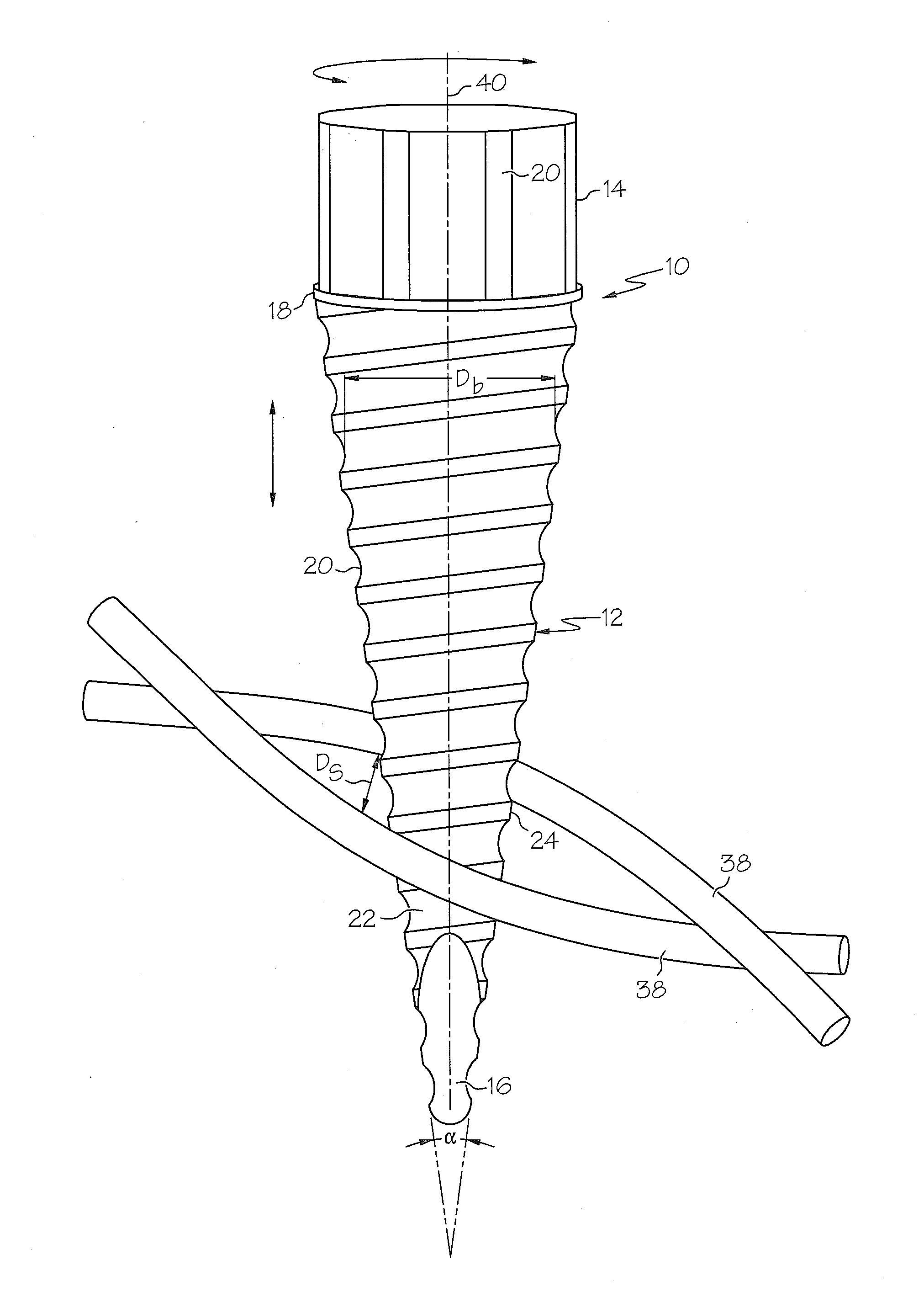
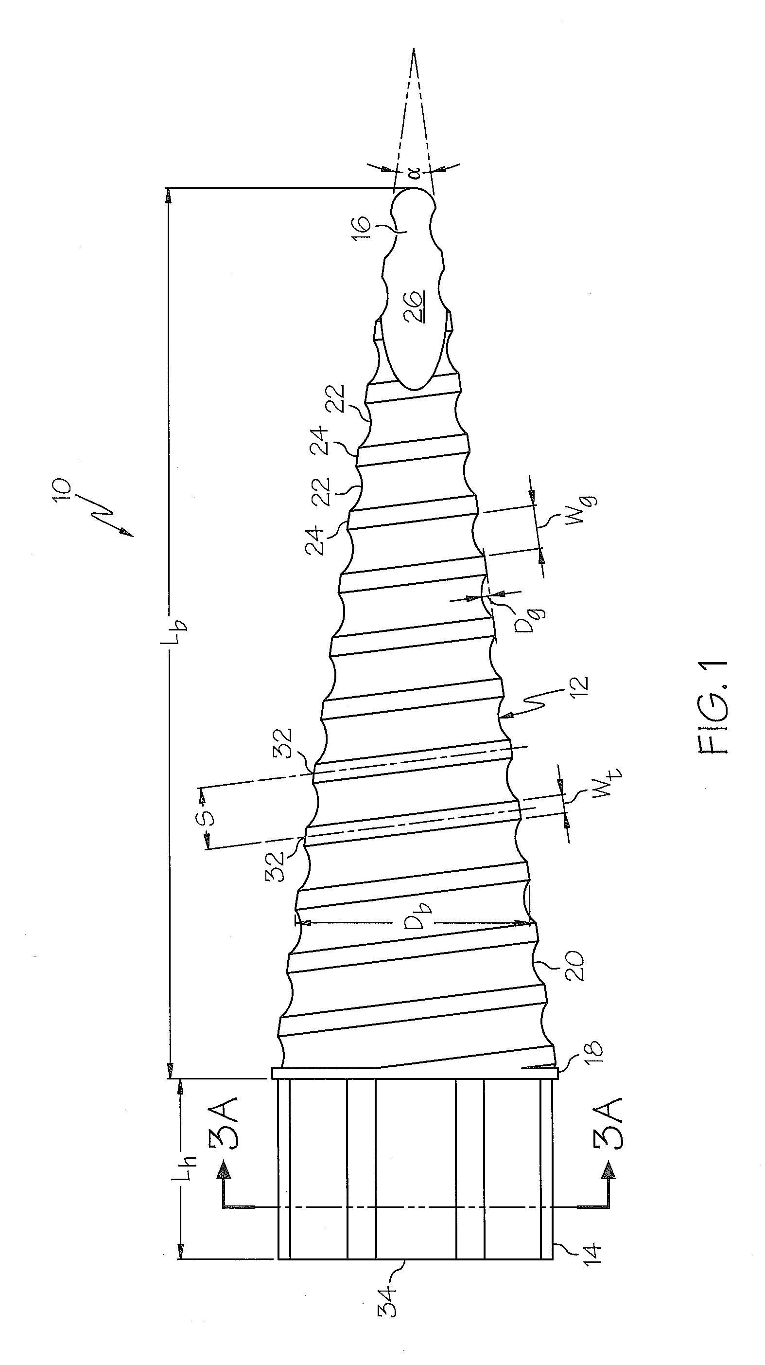
[0027]Turning to FIG. 1, an embodiment of the present power line spreading device 10 is illustrated. Power line spreading device 10 generally comprises a substantially conical body 12 and a handle 14. Body 12 includes a first end 16, a second end 18, an outer face 20, a length Lb, and a diameter Db. Body 12 also includes at least one s...


PUM

PropertyMeasurementUnit
vertex angleaaaaaaaaaa
lengthaaaaaaaaaa

Abstract

A power line spreading device used to separate the two conductor lines of a twisted pair conductor. The spreading device includes a substantially conical body and a handle. The body further includes a groove in an outer surface orientated in a conic spiral along a length of the body wherein the diameter of the conical body gradually increases from a first end to a second end. The spreading device is engaged with the two conductor lines proximate the first end, rotated about an axis of rotation whereby the groove acts to draw the two conductor lines from a first end toward a second end of the body. The gradual increase in diameter of the spreading device causes and maintains a desired spread distance between the two conductor lines of a twisted pair connector.

Description

CROSS-REFERENCE TO RELATED APPLICATIONS[0001]This Application is a Continuation-in-Part of and claims priority to U.S. patent application Ser. No. 13 / 013,134, filed on Jan. 25, 2011, to James Abel and S. Troy Snook entitled “Power Line Spreading Device,” currently pending, the entire disclosure of which is incorporated herein by reference.BACKGROUND OF THE INVENTION[0002]To more efficiently transmit electricity, a twisted pair conductor has been utilized by many utility companies. A twisted pair conductor generally comprises two standard, round conductor lines twisted around each other at approximately nine foot intervals. A twisted pair conductor is beneficial because it has lower maintenance, operating and inspection costs, a lower operating temperature, and reduces galloping. Further, a twisted pair conductor effectively resists wind induced motion in two ways. First, the constantly varying diameter due to the twisting drastically inhibits resonant vibration. Second, the low tors...

Claims


Application Information

Patent Timeline
Patent Type & Authority Applications(United States)
IPC IPC(8): H02G1/00B25B25/00
CPCD07B7/18H02G1/00Y10T403/556Y10T29/49Y10T403/70Y10T403/55D07B7/182
Inventor ABEL, JAMESSNOOK, S. TROY
Owner ENOUGH SAID
Why Eureka
Try Eureka