Optical characteristic measurement apparatus

a characteristic measurement and optical technology, applied in the direction of measurement devices, instruments, structural/machine measurement, etc., can solve the problem of difficult to determine the true best image plane position

Inactive Publication Date: 2012-10-04
CANON KK
View PDF1 Cites 0 Cited by
  • Summary
  • Abstract
  • Description
  • Claims
  • Application Information

AI Technical Summary

Benefits of technology

[0008]In order to solve the problem, according to the present invention, there is provided an optical characteristic measurement apparatus acquires a measurement value pertaining to an image characteristic of an optical system to be tested on a plurality of evaluation planes in proximity of an image plane of an object by the optical system to be tested, and measures an optical characteristic of the optical system to be tested based on each measurement value, comprising a measurement value correction unit correcting a measurement value pertaining to a width or a light intensity of one of a line spread distribution and a point spread distribution of a beam by the optical system to be tested, on the evaluation planes, wherein: in case where the measurement value pertains to the width of one of the line spread distribution and the point spread distribution of the beam, the image plane is regarded as an evaluation reference plane, and the measurement value correction unit outputs a corrected value such that when the evaluation plane approaches the optical system to be tested in comparison with the evaluation reference p

Problems solved by technology

In the case of evaluating the defocus characteristic of the optical system to be tested while varying one of the distance between an object and the optical system to be tested and the distance between the optical system to be tested and an evaluation apparatus, such as a screen and a camera, a following problem is caused.
This prob

Method used


Image

  • Optical characteristic measurement apparatus
  • Optical characteristic measurement apparatus
  • Optical characteristic measurement apparatus

Examples


first embodiment

[0023]Overall Configuration of Apparatus

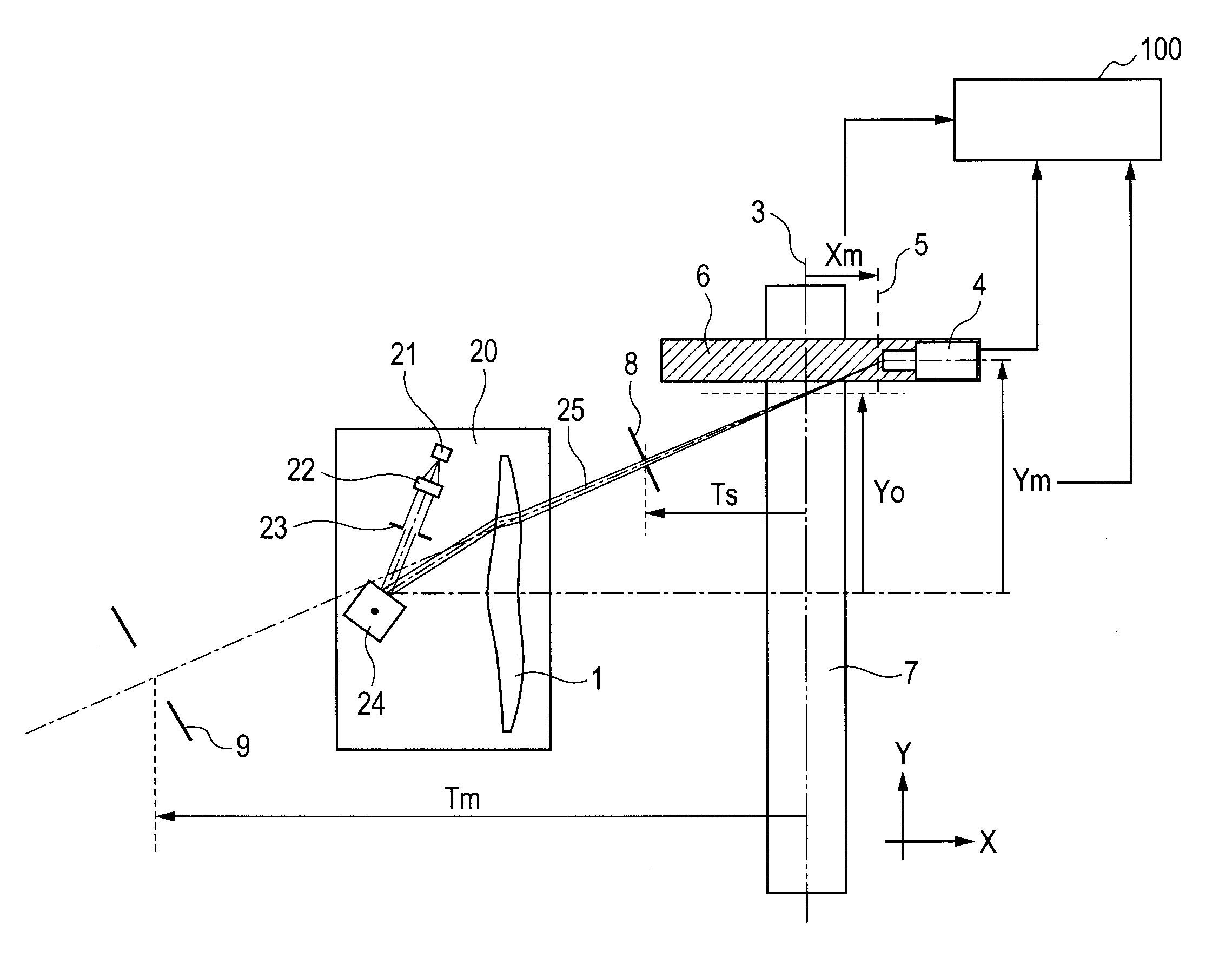
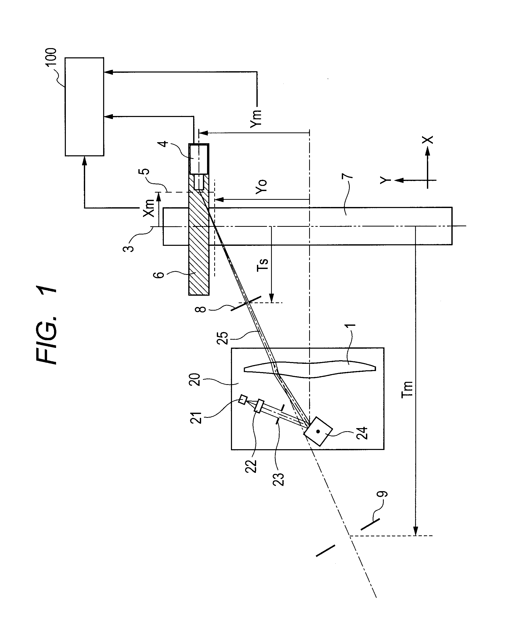
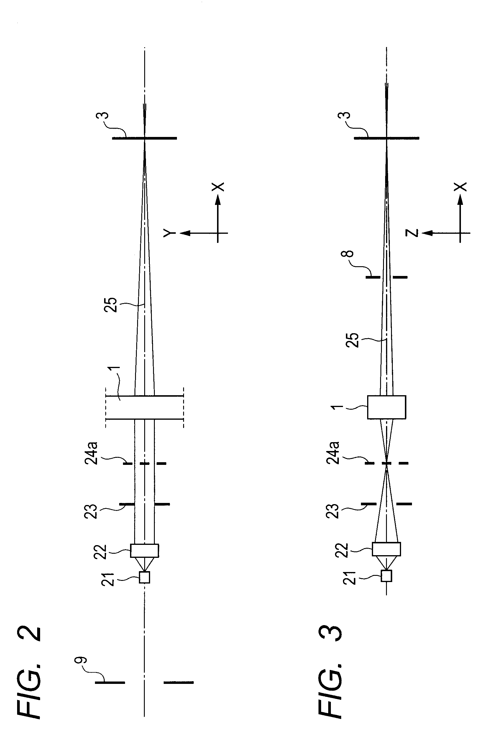
[0024]FIG. 1 illustrates an embodiment of application to an optical characteristic measurement apparatus of a laser scanning optical system. In this diagram, the X direction is referred to as a defocus direction, and the Y direction is referred to as an image height direction. For representation of characteristics of an optical system to be tested, the center line of a beam is referred to as a principal ray. A direction that includes the principal ray and is parallel to the plane of this sheet is referred to as a main scanning direction. A direction perpendicular to the plane of the sheet is referred to as a sub-scanning direction.

[0025]In FIG. 1, a lens 1 for laser scanning is an optical system to be tested. A measurement unit 20 includes the lens 1 for laser scanning and is a unit for measuring optical characteristics. The measurement unit 20 includes a semiconductor laser light source 21, as an object, and a light source optical system 22. ...

second embodiment

[0057]In the first embodiment, the measurement values are the LSF line widths in the main and sub-scanning directions. In this embodiment, the measurement values are the maximum intensities value Py and Pz of LSF in FIG. 4B. In the first embodiment, when the evaluation plane is provided in ahead of and behind of the reference plane as the image plane in the first embodiment to measure the beam width, correction is performed in consideration of the image magnification. On the other hand, in measurement of the light intensity of the beam, correction is performed using a correction coefficient that is a reciprocal of a correction coefficient pertaining to the beam width. This is because, in any defocus state, the integral value of light intensity, i.e. energy, is constant, and the product of the beam width and the light intensity of the beam is maintained constant.

[0058]Provided that Pya and Pza are LSF widths in the main and sub-scanning direction after correction, these values are co...

third embodiment

[0061]In the second embodiment, the measurement value is the maximum intensity of LSF. In this embodiment, the measurement value is the maximum intensity of PSF. In this embodiment, it is sufficient that correction of the light intensity of the beam which is inversely proportional to the correction of the beam diameter in the main and sub-scanning directions is performed simultaneously in the main and sub-scanning directions. That is, provided that Io is the measurement value before correction (maximum intensity of PSF) and Ia is the corrected value after correction,

Ia=(Tm−Xm) / Tm×(Ts−Xm) / Ts×Io.  (6)

[0062]It is here provided that the product of the distance Tm in the main scanning direction from the evaluation reference plane to the exit pupil and the distance Ts in the sub-scanning direction from the evaluation reference plane to the exit pupil is Kyz, the distance in the main scanning direction from the exit pupil to the evaluation plane is Ly, and the distance in the sub-scanning ...


PUM


Abstract

An optical characteristic measurement apparatus acquires a measurement value pertaining to an image characteristic of an optical system to be tested on a plurality of evaluation planes, and measures an optical characteristic, comprising a measurement value correction unit correcting a measurement value pertaining to a width or a light intensity of one of a line spread distribution and a point spread distribution of a beam, on the evaluation planes, wherein: in case where the measurement value pertains to the width, the image plane is regarded as an evaluation reference plane, and the measurement value correction unit outputs a corrected value; in case where the measurement value pertains to the light intensity, the image plane is regarded as an evaluation reference plane, and the measurement value correction unit also outputs a corrected value; and the optical characteristic of the optical system to be tested is measured based on the corrected value.

Description

BACKGROUND OF THE INVENTION[0001]1. Field of the Invention[0002]The present invention relates to an optical characteristic measurement apparatus for recognizing the best image plane position from the defocus characteristic of an optical system to be tested.[0003]2. Description of the Related Art[0004]In every optical field irrespective of a specific field to which an optical system is applied, an image condition is observed while moving a camera in the optical axis direction in proximity to a target image plane of an optical system to be tested, in order to measure the focusing position and the focal depth performance of the optical system to be tested. The measurement allows recognition of the difference between the best image plane position and the target image plane position of the optical system to be tested, and enables the difference to be reduced by correcting the shapes of components and adjusting the positions according to the value, as necessary. Instead thereof or in addi...

Claims


Application Information

Patent Timeline
IPC IPC(8): G01B11/02
CPCG01M11/0257
Inventor ANDO, TOSHINORI
Owner CANON KK
Why Eureka
Try Eureka