
Device and method for determining s-wave attenuation in near-surface condition

a near-surface condition and s-wave technology, applied in the direction of measuring devices, scientific instruments, instruments, etc., can solve the problems of time-lapse 4d seismic acquisition and repeatability challenges

Active Publication Date: 2012-08-02
CGGVERITAS SERVICES
View PDF9 Cites 16 Cited by
  • Summary
  • Abstract
  • Description
  • Claims
  • Application Information

AI Technical Summary

Benefits of technology

"The patent describes a method for analyzing seismic data to determine the primary and ghost components of S-waves recorded in near-surface conditions. This allows for the creation of an image of the subsurface based on these components. The S-waves form a plane wave and the near-surface conditions describe the part of the subsurface between the receiver and the surface of the earth. The technical effect of this invention is the improved accuracy and accuracy of seismic data analysis for the evaluation of oil and gas reservoirs."

Problems solved by technology

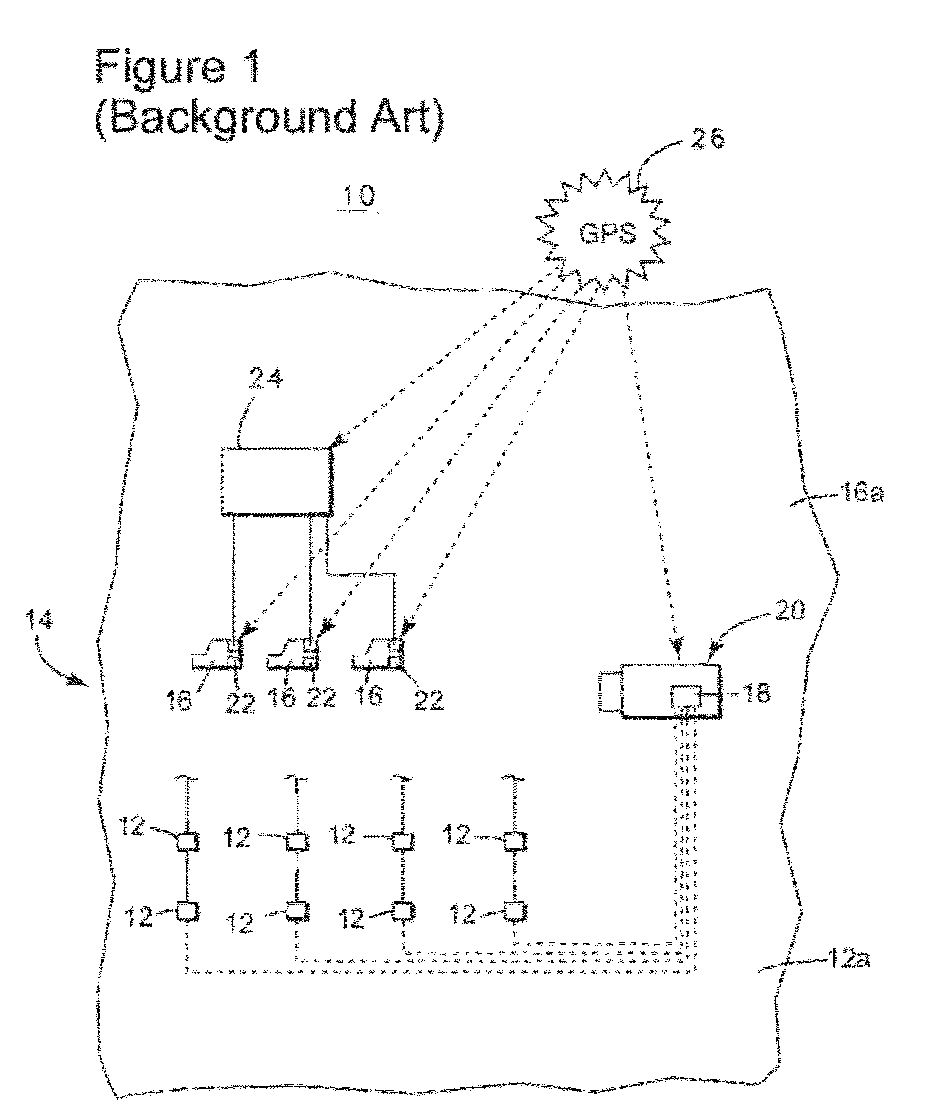
Although repeatability of source and receiver locations is generally easier to achieve onshore, the variations caused by changes in near-surface can be significantly larger than reservoir fluid displacement, making time-lapse 4D seismic acquisition and repeatability challenging.

Method used


Image

  • Device and method for determining s-wave attenuation in near-surface condition
  • Device and method for determining s-wave attenuation in near-surface condition
  • Device and method for determining s-wave attenuation in near-surface condition

Examples


Embodiment Construction

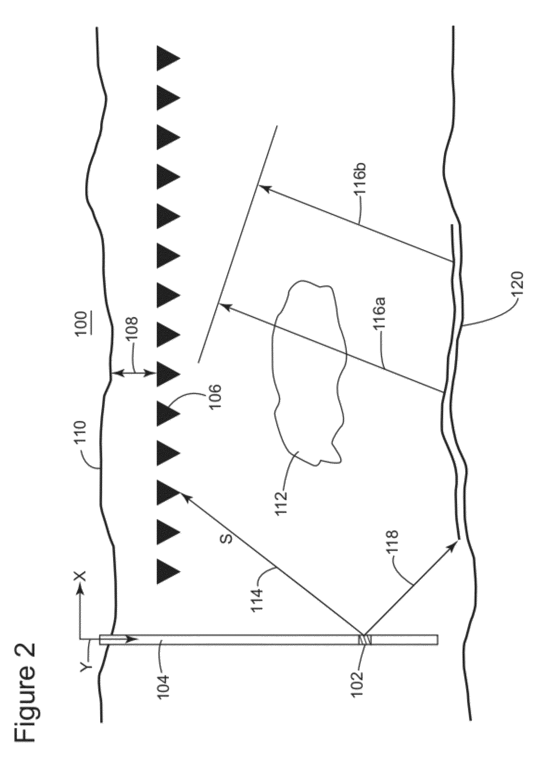
[0025]The following description of the exemplary embodiments refers to the accompanying drawings. The same reference numbers in different drawings identify the same or similar elements. The following detailed description does not limit the invention. Instead, the scope of the invention is defined by the appended claims. The following embodiments are discussed, for simplicity, with regard to the terminology and structure of a seismic system having a dipole source and buried three-dimensional receivers. However, the embodiments to be discussed next are not limited to a dipole source and may be applied to other types of sources.

[0026]Reference throughout the specification to “one embodiment” or “an embodiment” means that a particular feature, structure or characteristic described in connection with an embodiment is included in at least one embodiment of the subject matter disclosed. Thus, the appearance of the phrases “in one embodiment” or “in an embodiment” in various places througho...


PUM


Abstract

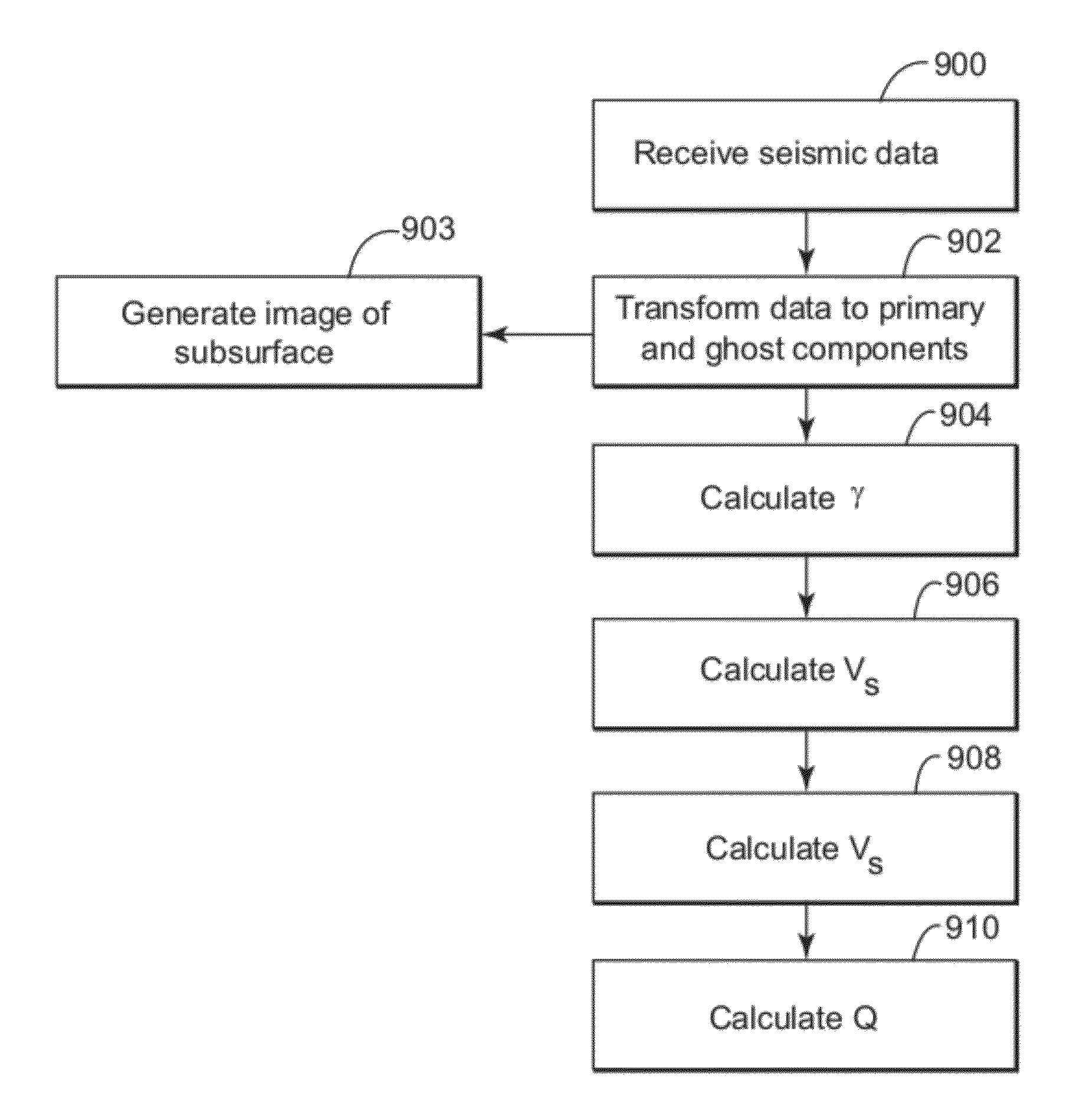
Computing device and method for determining primary and ghost components from S-waves recorded in near-surface conditions, wherein the S-waves are refracted or reflected from a structure in a subsurface. The method includes a step of receiving seismic data (R, V) with regard to the S-waves, wherein the seismic data includes vertical and radial components recorded with a buried three-component receiver; a step of calculating with a processor a primary component (P) and a ghost component (G) from the vertical and radial components; and a step of computing an image of a subsurface based on the primary and ghost components (P, G). The S-waves form a plane wave.

Description

CROSS REFERENCE TO RELATED APPLICATIONS[0001]This application claims priority and benefit from Provisional Patent Application No. 61 / 437,904, filed Jan. 31, 2011, for “Determining S-Wave Attenuation in Near Surface,” the entire contents of which are incorporated herein by reference.BACKGROUND[0002]1. Technical Field[0003]Embodiments of the subject matter disclosed herein generally relate to methods and systems and, more particularly, to mechanisms and techniques for determining a Q-factor of S-waves near a surface of the earth.[0004]2. Discussion of the Background[0005]During the past years, interest in monitoring oil and / or gas reserves has increased, Time-lapse (or 4D) seismic monitoring of producing oil fields is an accepted method for optimization of field development and product recovery, providing significant improvements in recovery rates and savings in drilling costs.[0006]Time-lapse seismic reservoir monitoring is the comparison of 3D seismic surveys at two or more points i...

Claims


Application Information

Patent Timeline
Patent Type & Authority Applications(United States)
IPC IPC(8): G01V1/36
CPCG01V1/28G01V2210/56G01V2210/612
Inventor MEERSMAN, KRISTOF DE
Owner CGGVERITAS SERVICES
Learn More