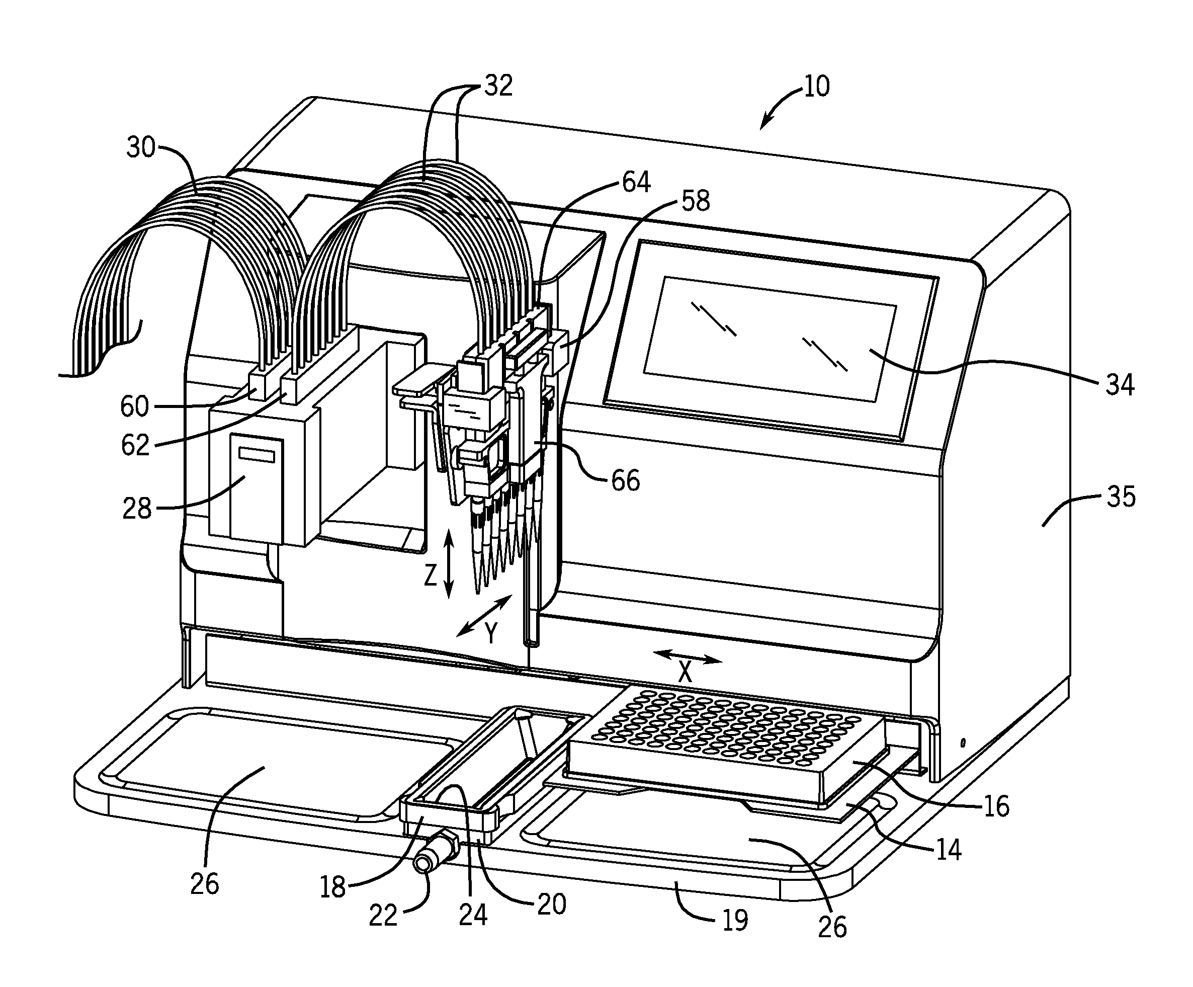
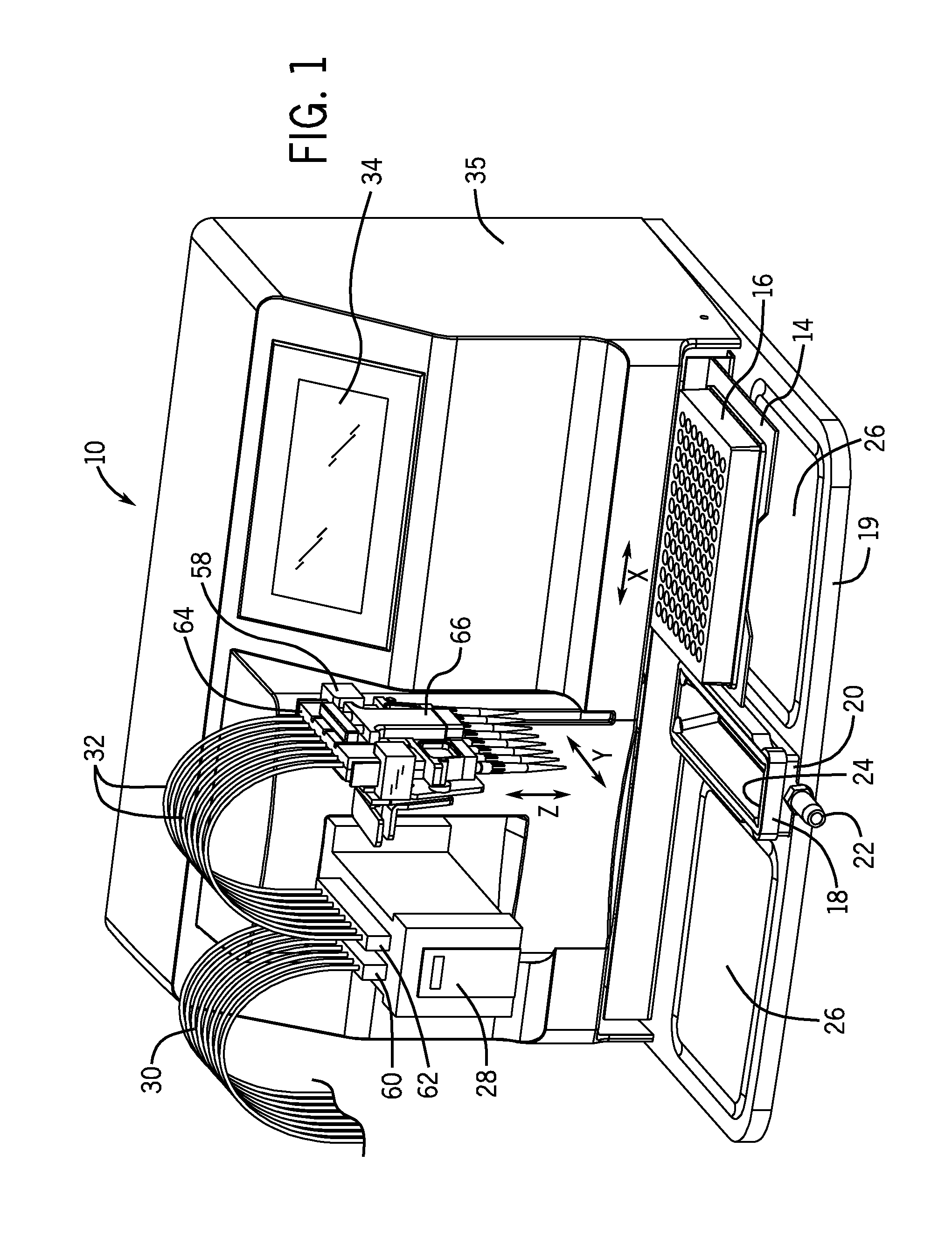
[0007]In an exemplary configuration, the array of pipette tip mounting shafts are located at a fixed location along the X-axis, and the system includes a motorized drive to lower and lift the array of pipette tip mounting shafts at this fixed location along the X-axis. Desirably, a reagent reservoir is located at this location below the array of pipette tip mounting shafts. To begin operation, disposable pipette tips are mounted onto the array of tip mounting shafts. Then as mentioned, the controller directs the system to move the disposable pipette tips into liquid reagent contained within the reagent reservoir, and drives the
peristaltic pump in a reverse direction in order to aspirate liquid into the disposable pipette tips via air displacement. The pipette tips are then positioned over a respective column of wells and the controller directs the peristaltic pump to move in the forward direction in a controlled manner to dispense a metered amount of liquid from the disposable pipette tips into the respective wells in the wellplate on the platform. In an 8-channel system, the disposable pipette tips are preferably capable of aspirating and dispensing up to 300 ml. In a 16-channel system, the disposable pipette tips are preferably capable of aspirating and dispensing up to 125 ml. Those skilled in the art will appreciate that the invention as described avoids the need for filling the flexible tubes of the tube set with liquid reagent in order to prime the system, and that it also avoids waste reagent in the flexible tubes after filling has been completed. Another
advantage of the invention is the ability of the system to aspirate reagent from a column of wells in a well plate, and dispense the reagent in another column of the well plate thereby enabling the system to conduct serial dilutions.
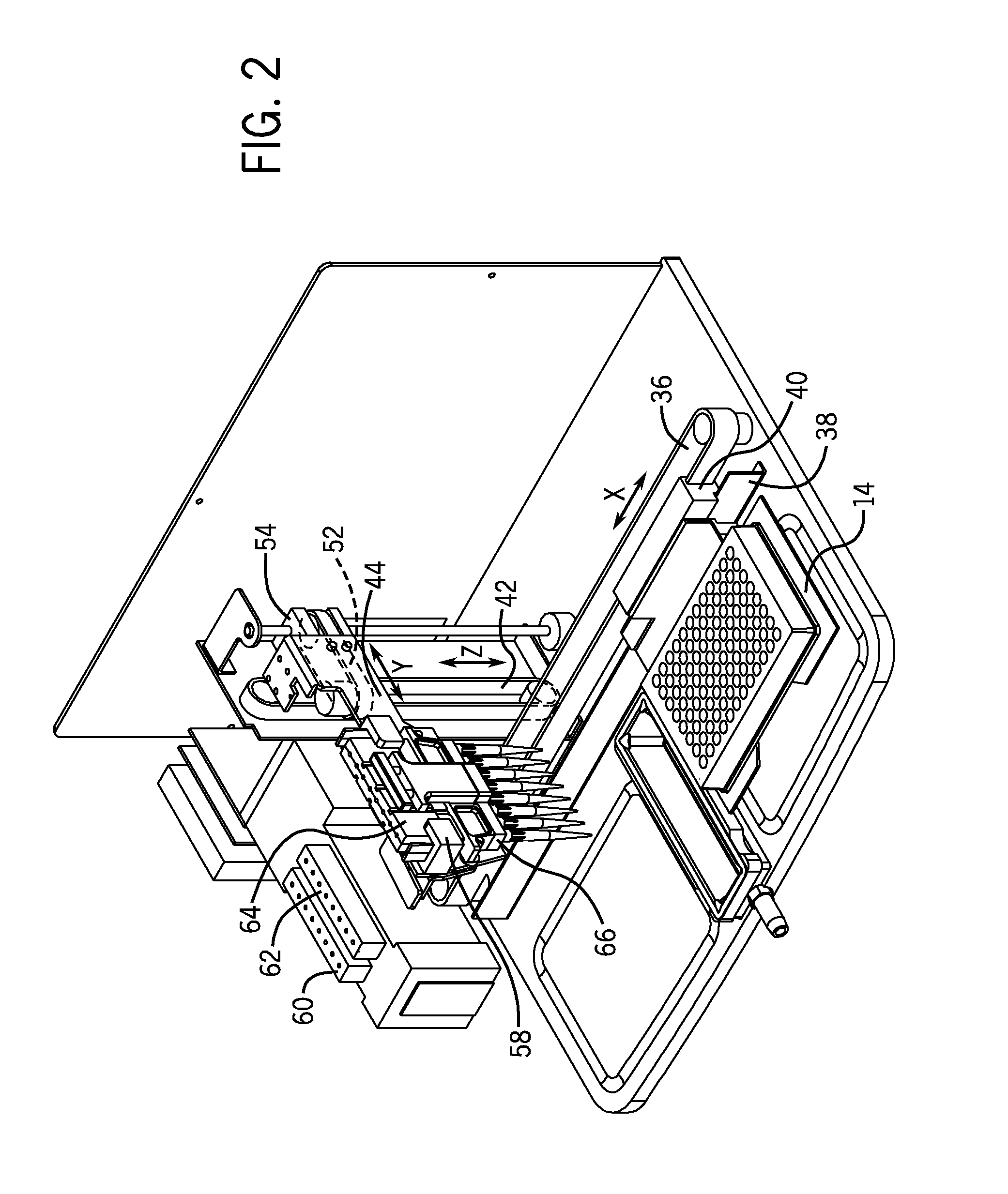
[0008]It is desirable that the
tubing set include a
nozzle cartridge having a plurality of
interfacing nozzles similar to filling nozzles used in the prior art as well as the flexible tubes connected to the
cartridge and the
interfacing nozzles. It is further desired that the array of pipette tip mounting shafts be mounted on a mounting shaft
cartridge that is attachable to the
nozzle cartridge. Preferably, the mounting shaft cartridge can be easily removed from the instrument to enable disposable pipette tips to be loaded and ejected with the cartridge off the instrument. A latching mechanism attaches the pipette tip mounting shaft cartridge to the
interfacing nozzle cartridge such that the sealing rings or a
gasket are compressed to provide a fluid tight seal when the cartridges are latched together. It is further preferred that the tip mounting shaft cartridge includes a stripping mechanism in order to mechanically strip disposable pipette tips from the mounting shafts on the cartridge. The system can be operated in a flow-through manner if desired by detaching the mounting shaft cartridge.
[0009]In a preferred embodiment, the wellplate filling system has a motorized Z-axis drive mechanism to drive the
linear array of pipette mounting in a vertical up or down direction. It is possible however within the scope of the invention to move the
linear array of pipette tip mounting shafts vertically up and down by a manual mechanism. It is also preferred that the wellplate filling system include a motorized Y-axis drive mechanism that moves the linear array of pipette tip mounting shafts horizontally along a Y-axis in order to reposition the pipette tip mounting shafts in a direction perpendicular to the X-axis in which the wellplate platform is indexed, such as for repositioning the pipette tip mounting shafts to different wells located in the same X-axis location.
[0010]The system also desirably contains
software to direct the drive mechanisms to touch-off drops of liquid from the end of the respective pipette tips into an array of wells on wellplate after dispensing liquid into the array of wells. This feature requires coordination between the Z-axis drive mechanism which vertically lifts and lowers the pipette tips and the X-axis drive mechanism that indexes the position of the wellplate platform.
[0011]The centerline to centerline distance of the pipette tip mounting shafts is preferably 9 mm for an 8-channel system. An 8-channel system with 9 mm centerline to centerline spacing between the mounting shafts can be configured with a Y-axis
motor drive (or manual Y-axis shift) to shift the pipette tip mounting shafts in order to fill all 16 wells in a column on a 384 wellplate. Alternatively, for filling 384 wellplates, a 16-channel system with 4.5 mm centerline to centerline distance can be used. Of course, 1536 wellplates can be filled by shifting the array of pipette tip mounting shafts in either an 8-channel or 16-channel system along a Y-axis.
[0012]In another aspect of the invention, a multi-channel wellplate filling system generally as described above is capable of being converted into a wellplate washing
station. In this regard, the wellplate filling
station includes a plate washing head having multiple pairs of needles comprising a wash needle and a vacuum needle. The vacuum needle in each pair desirably extends further down than the wash needle. The multiple pairs of needles are arranged in a linear array, such as a linear array of 8 pairs of needles for an 8-channel system. A washing tube set having multiple flexible tubes is in fluid communication with the wash needles on the plate washing head. The peristaltic pump pumps washing fluid through the flexible tubes on the plate washing head. A vacuum source is connected to the vacuum needles on the plate washing head as well. In use, the array of needle pairs is lowered into wells on a wellplate on the wellplate platform. The peristaltic pump pumps washing fluid into the respective wells, and control of the X and Y position of the wellplate moves the needle pairs around each well, e.g., with circular
relative motion, during which time the vacuum source is activated so that the vacuum needles suck the washing fluid out of the respective wells. The system control then moves the needle pairs to the next set of wells to be filled with washing fluid and vacuumed. The plate washing head preferably includes a manifold having passageways between the vacuum needles and the vacuum source. Thus, the multi-channel wellplate filling system can be conveniently converted into a wash station by replacing a mounting shaft cartridge and tube set with a plate washing head and tube set, supplying washing fluid to the flexible tubes passing through the peristaltic pump and
hooking the plate washing head up to a vacuum source. After washing is completed, it will be desirable to rinse the wash station tubing set by pumping rinse fluid through the tubing set. All of these components and functions are desirably controlled by the system
electronic control unit.
