Smart node

a smart node and node technology, applied in the direction of analysing/displaying, generating/distributing signals, instruments, etc., can solve the problems of significant power consumption and the possibility of never being completely powered down in critical circuits, so as to prolong the life of power supply and enhance power efficiency

Inactive Publication Date: 2012-08-02
ASLAN ROARING LLC
View PDF14 Cites 19 Cited by
  • Summary
  • Abstract
  • Description
  • Claims
  • Application Information

AI Technical Summary

Benefits of technology

[0003]One aspect of the invention relates to a system and method of dynamically monitoring and managing power distribution at a point of delivery of power to one or more circuits. For example, power distribution may be monitored and / or managed at a circuit breaker panel of a building or set of buildings, or at other locations. In some implementations, the system and / or method may be implemented in a circuit breaker panel of a residential, commercial, and / or military building in a retrofitted manner. The granular monitoring and / or dynamic management of power distribution described herein may enhance power efficiency, preserve power supply life (e.g., battery life), and / or provide other enhancements over conventional circuit breaker panel configurations.

Problems solved by technology

Power wastage, such as with standby power usage, may account for a significant percentage of power consumption.
For example, some critical circuits may never be completely powered down for safety reasons, regardless of instructions to the contrary from a user or the trigger module.

Method used


Image

  • Smart node
  • Smart node
  • Smart node

Examples


Embodiment Construction

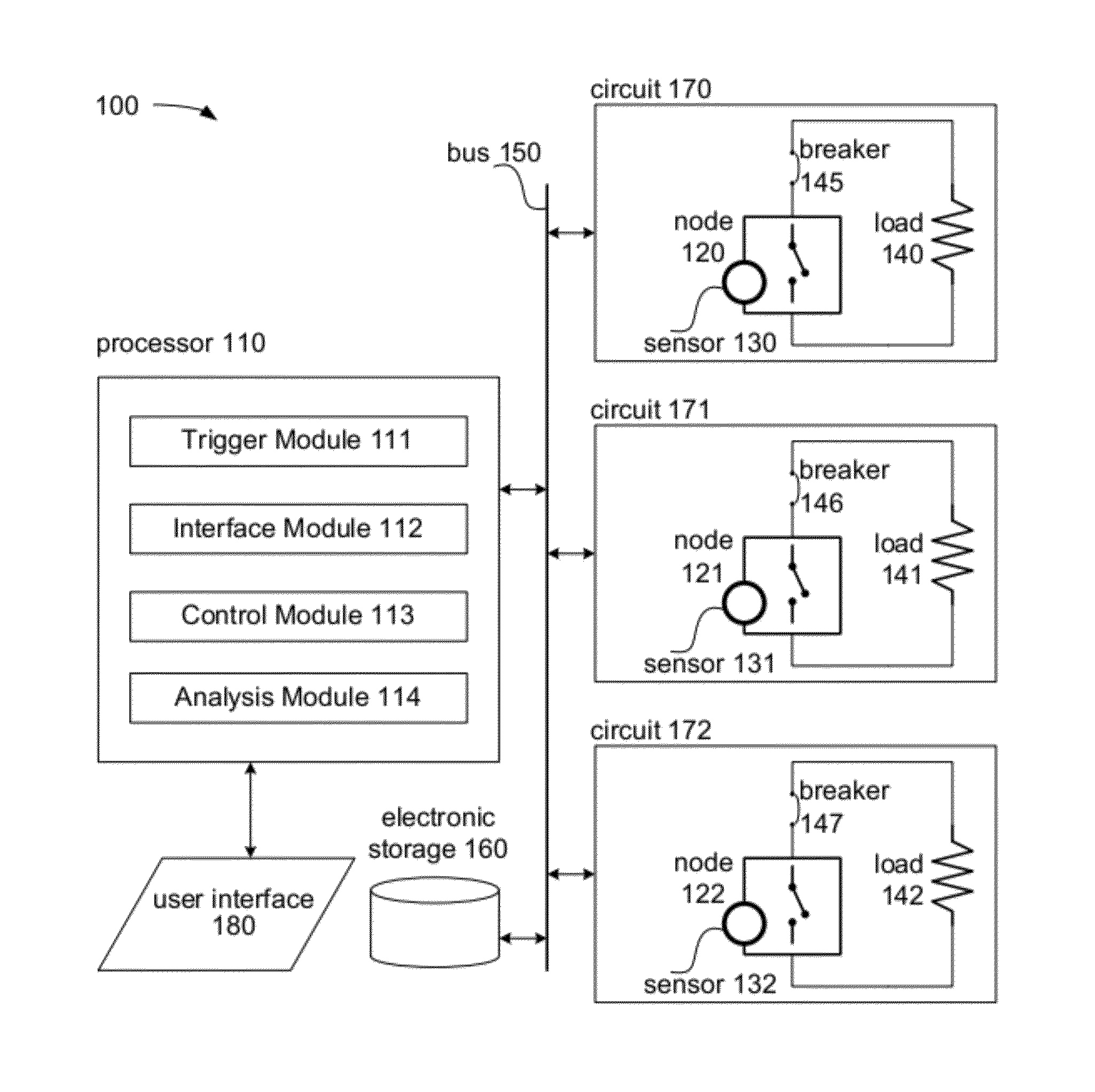
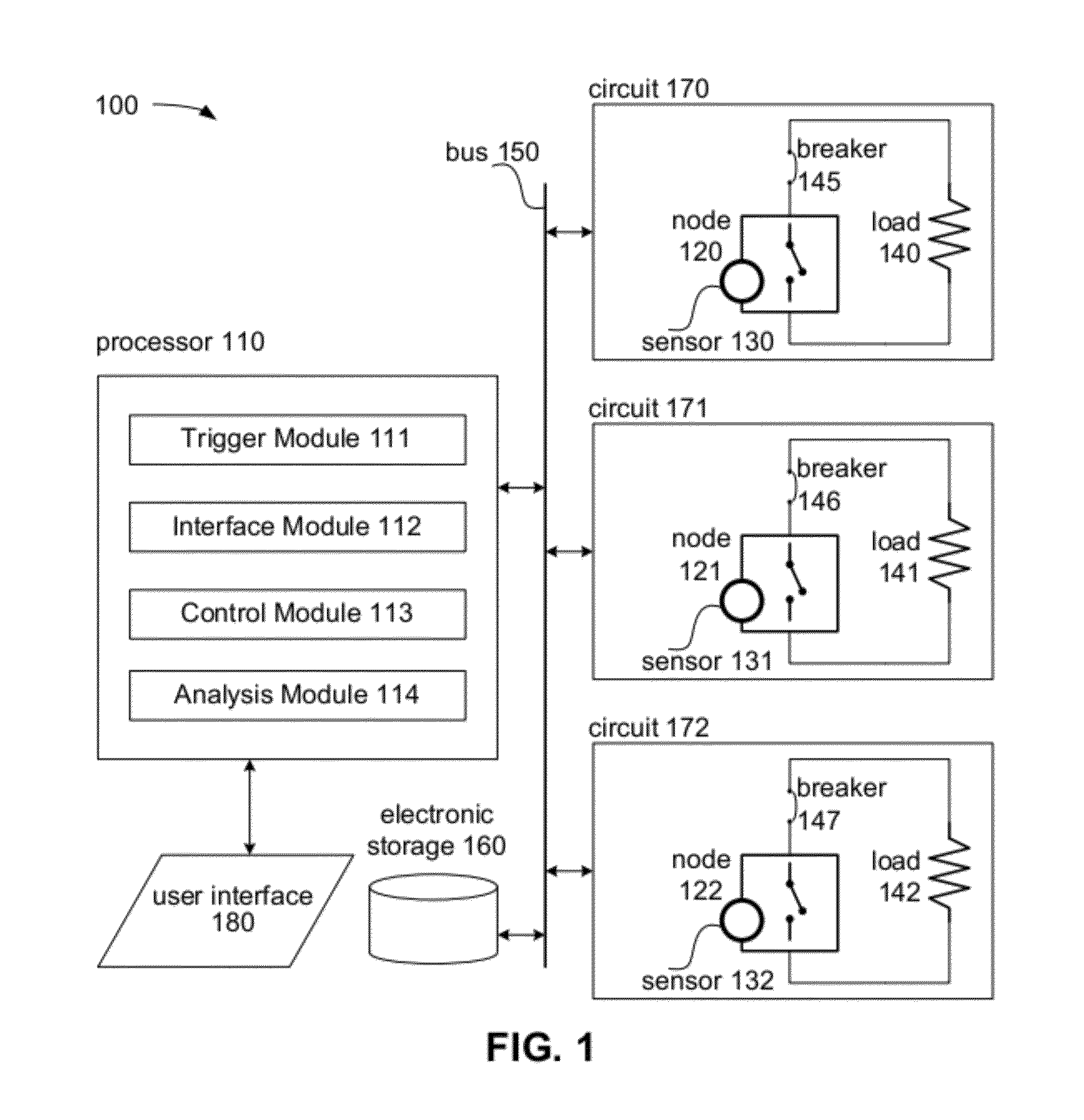
[0018]FIG. 1 illustrates an exemplary implementation of a power management system 100. Power management system 100 may be configured to control power delivery from a power supply to a circuit, and may include one or more of electronic storage 160, bus 150, processor 110, user interface 180, one or more circuits such as circuit 170, circuit 171, and circuit 172, and / or other components.

[0019]Power management system 100 may receive electrical power from at least one power supply. The power supply, or power supplies, may comprise any source or sources of electrical power, including the utility grid. For example, the power supply may include a remote power generation installation such as a power plant. Such a power plant may include coal-burning power plant, a nuclear power plant, and so on. As another example, the power supply may include a power generator that converts tidal energy of the ocean into power that is usable within power management system 100. Additionally or alternatively...


PUM


Abstract

Systems for reducing power usage and/or wastage use sensors to gather information about a circuit and its usage. Triggers are identified based on the information from the sensors, and subsequently used to control power delivery by reversibly effectuating energization and deactivation of particular circuits through smart nodes.

Description

FIELD OF THE INVENTION[0001]The invention relates to electrical power management. In particular, the invention relates to controlling and monitoring power delivery to circuits via a smart node.BACKGROUND OF THE INVENTION[0002]Typically local power networks (e.g., electrical infrastructure of a building and / or campus) include power lines, circuits, a distribution board, outlets, loads, as well as circuit breaker panels and / or breaker boxes, which lack dynamic functionality. As such, electrical power management may be performed either manually, or with timers located at individual power outlets within the local power network. Power wastage, such as with standby power usage, may account for a significant percentage of power consumption.SUMMARY[0003]One aspect of the invention relates to a system and method of dynamically monitoring and managing power distribution at a point of delivery of power to one or more circuits. For example, power distribution may be monitored and / or managed at ...

Claims


Application Information

Patent Timeline
Patent Type & Authority Applications(United States)
IPC IPC(8): G06F1/14
CPCY02B90/244Y02B90/241H02J3/14Y04S20/327G01D4/002Y04S20/32H02J2310/12Y02B90/20Y04S20/00Y04S20/222Y02B70/3225G01D2204/12H02J2310/14Y04S20/30G05B15/02H02J3/00
Inventor PUGH, WILLIAM CLAYTONALBARRAN, RICHARD DANIELCRAIG, JASON BRUCE
Owner ASLAN ROARING LLC
Why Eureka
Try Eureka