Magnetic wheel

a technology of magnetic wheels and wheels, applied in the field of magnetic wheels, can solve the problems of difficult dislocation and limit to the steepness of the travel path, and achieve the effect of preventing backward rolling of the wheel(s) and increasing traction efficiency

Active Publication Date: 2012-08-09
MAGSWITCH TECH WORLDWIDE PTY LTD
View PDF3 Cites 59 Cited by
  • Summary
  • Abstract
  • Description
  • Claims
  • Application Information

AI Technical Summary

Benefits of technology

[0030]Vis a vis the above described prior art magnetic wheels, the mass associated with the magnetic flux source is no longer subject to rotation with the wheel, thereby reducing inertia moments at the wheel structure proper, with all the concomitant advantages which such reduced wheel mass brings with it. Physical decoupling of the wheels from the magnetic flux source also enables greater flexibility in devising or designing the flux source itself.
[0077]In a vehicular embodiment incorporating four or more pole wheels, wherein a switchable permanent magnet device is associated with one wheel pair, provision of a suitable mechanism that enables the selective switching on and off (or variation of the magnetic field intensity output) of the individual switchable magnets provides a number of advantages. Not only will such selective ‘magnetic activation and deactivation’ of individual wheel pairs facilitate operational disengagement of the vehicle from the substrate, it will also facilitate the vehicle being able to climb over step-like obstacles or transitions between a horizontal and a steeply inclined or vertical surface, in that forward pair of wheels reaching such path change location may be ‘demagnetised’ thereby to render them magnetically inoperative, whereby they can then lift-off from the initial surface and engage the inclined surface, whereupon they may be ‘remagnetised’ and allow the vehicle to transition onto the inclined surface. The rearward located wheel pair will be switched accordingly as it too reaches the path discontinuity.

Problems solved by technology

Whilst friction enhancing wheel and track coatings may be used to increase adherence of the vehicle to the surface in order to allow the vehicle to climb or descend along steep inclines, there are limits to the steepness of the travel path which such vehicle may safely master without tipping over or sliding in uncontrolled manner.
The stronger planar surfaces of objects are ‘forced’ together by a magnetic attraction force, the more difficult it is to displace them relative to one another whilst remaining attached to one another, by exerting a force perpendicular to the attracting force vector, for any given coefficient of friction which applies for the pairing of materials of the two objects.
In practical terms, and in light of the above description of prior art magnetic wheel constructs, a technical challenge still exists in devising methods and arrangements of magnetic flux transfer from a magnet, as a source of magnetic force to attach one object to another, through a wheel structure into a magnetically attractive body, to meet specified operational load carrying capacity or retention requirements.

Method used


Image

  • Magnetic wheel
  • Magnetic wheel
  • Magnetic wheel

Examples


Embodiment Construction

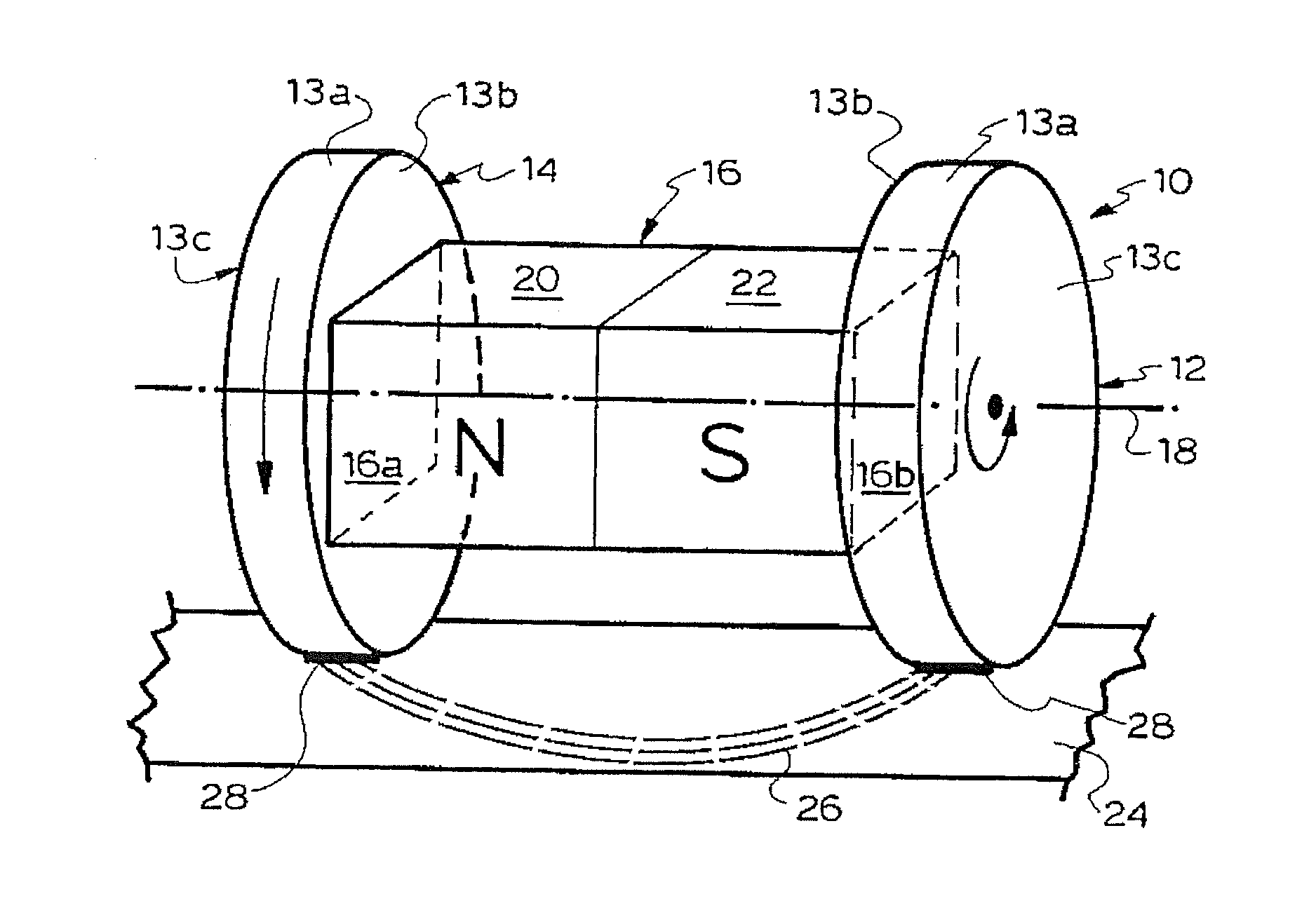
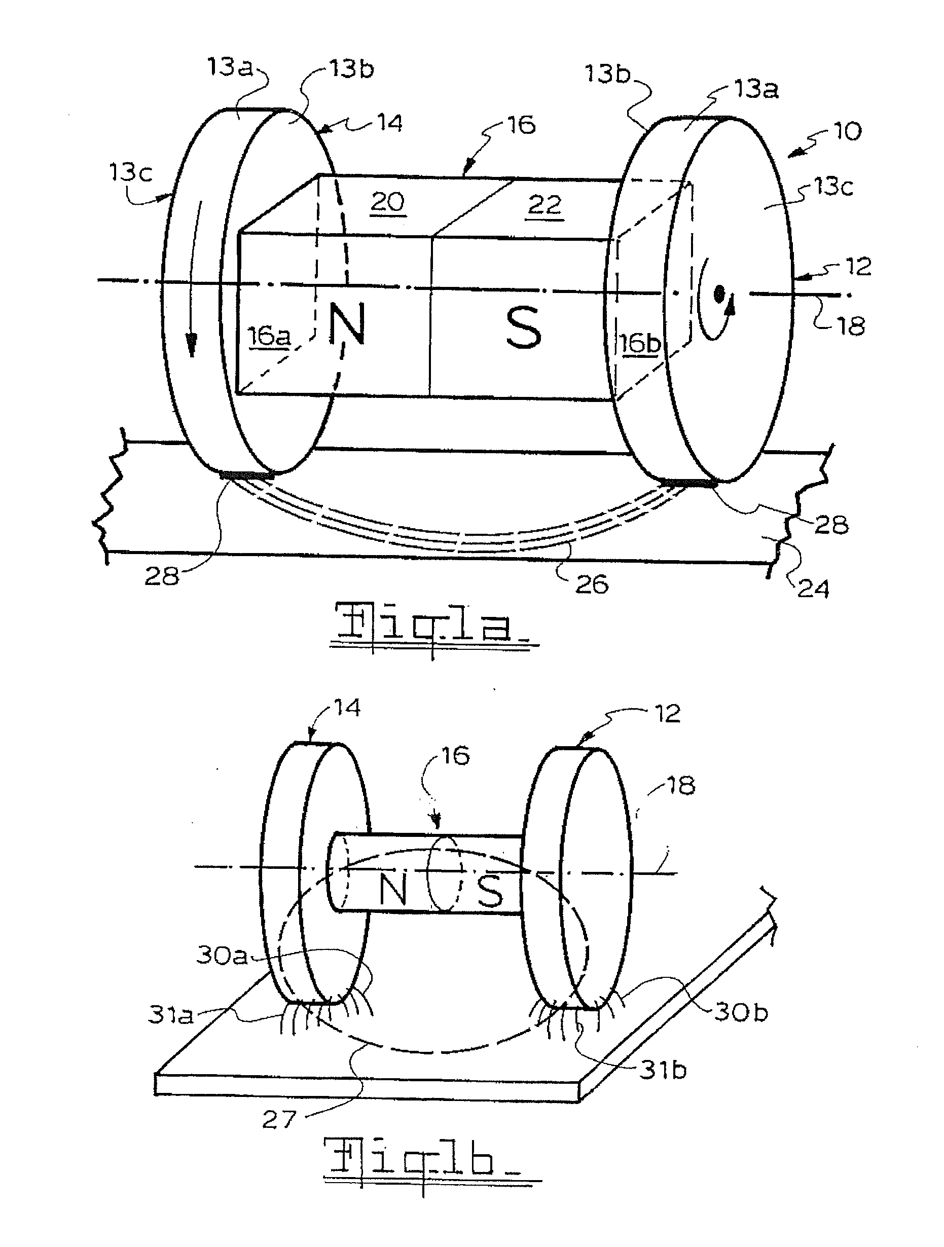
[0087]A basic magnetic wheel unit as illustrated in FIGS. 1a and 1b has already been described above. Such units can be incorporated in numerous and different machines and appliances. It should be noted that the active magnetic material (ie permanent magnets) or other magnetic flux source (eg electromagnet) can be received within a dedicated housing; thus, the actual shape of the magnetic flux unit 16 in FIGS. 1 and 2 is illustrative only and not representative of the actual shape of such units.

[0088]As can be best understood by having reference to FIGS. 2a to 2c, depending on the number of and specific types of dipole magnets employed as magnetic flux source, magnetic wheel units having different pole wheel numbers and arrangements are possible.

[0089]FIG. 2a illustrates a twin wheel configuration unit 10 utilising a single magnet 16 and two rotatable pole wheels 14, 16 as previously described with reference to FIG. 1a.

[0090]FIG. 2b illustrates an arrangement with two pairs of pole...


PUM

PropertyMeasurementUnit
thicknessaaaaaaaaaa
thicknessaaaaaaaaaa
width×90aaaaaaaaaa

Abstract

Magnetic circuit that has (a) a source of magnetic flux which includes an electromagnet or one or more permanent magnets, (b) at least two oppositely polarisable pole extension bodies associated with the magnetic flux source, the bodies being disc, wheel, roller or similarly shaped with an outer circumferential surface and held rotatable about respective axes of rotation, and (c) a ferromagnetic counter body which is arranged to cooperate with the pole extension bodies such as to provide an external flux path for the magnetic flux when in magnetic proximity or contact with the circumferential surface of the pole extension bodies, which is characterised in that the magnetic flux source is held stationary relative to the rotatable pole extension bodies.

Description

FIELD OF THE INVENTION[0001]The present invention relates to the field of magnetics, in particular to the use of magnetic force to attach one object to another whilst allowing movement of the objects relative to one another in a magnetically attached state.BACKGROUND OF THE INVENTION[0002]There are numerous situations and applications where it is desirable and / or necessary to secure or support one object to or on another object whilst allowing for freedom of translational or rotational movement of these objects relative to one another.[0003]In the field of material handling, for example, roller conveyors are used to transport sheet metal and other ferromagnetic work pieces from one location to another. Gravity forces are relied upon to ensure the work pieces remain on the conveyor rollers (some of which may be driven and others being idle rollers) as these are transported, and thus such conveyor systems will mostly have roller transport paths extending substantially in a common hori...

Claims


Application Information

Patent Timeline
Patent Type & Authority Applications(United States)
IPC IPC(8): H01F7/02
CPCB60L13/04B66C1/04B60L2200/26B66C1/08B66C7/02B66C1/06B65G39/10
Inventor KOCIJAN, FRANZ
Owner MAGSWITCH TECH WORLDWIDE PTY LTD
Why Eureka
Try Eureka