Marine fender

a fender and marine technology, applied in the field of marine fender, can solve the problems of marine fender reaction force, high friction coefficient of rubble, vessel, etc., and achieve the effects of low and uniform compression surface pressure, excellent wear characteristics, and small siz

Inactive Publication Date: 2012-08-09
BRIDGESTONE CORP
View PDF4 Cites 7 Cited by
  • Summary
  • Abstract
  • Description
  • Claims
  • Application Information

AI Technical Summary

Benefits of technology

[0026]According to the invention, there can be provided a marine fender comprising a shock receiving portion inclusive of a shock receiving resin board and a pair of rubbery leg portions and having (1) a specific relation between width W of the shock receiving portion and height H of the fender and (2) a specific relation among thickness h1 of the shock receiving portion, height h2 of the leg portion, thickness t of the leg portion and height H of the fender, and being low and uniform in the compression surface pressure and excellent in the wear characteristics.
[0027]According to the invention, there can also be provided a marine fender comprising a shock receiving portion inclusive of a shock receiving resin board and a shock receiving rubber board, a pair of rubbery leg portions, a backup plate and a fastener member and having (1) a specific relation between width W of the shock receiving portion and height H of the fender and (2) a specific relation among thickness h1 of the shock receiving portion, height h2 of the leg portion, thickness t of the leg portion and height H of the fender, and being low and uniform in the compression surface pressure, small in the deterioration of the resistance to compression load even if the shock receiving portion is worn and easy in the replacement of the shock receiving board.

Problems solved by technology

However, rubber is high in the friction coefficient with iron mainly constituting an outer surface of the vessel (usually 0.4) and is worn by rubbing, scratching, chipping or the like based on the behavior of the vessel in shear direction.
Also, the vessel is subjected to reaction force from the marine fender during the contacting with the marine fender attached to the quay wall.

Method used


Image

  • Marine fender
  • Marine fender
  • Marine fender

Examples


Embodiment Construction

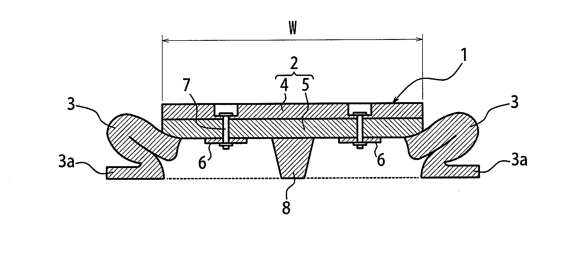
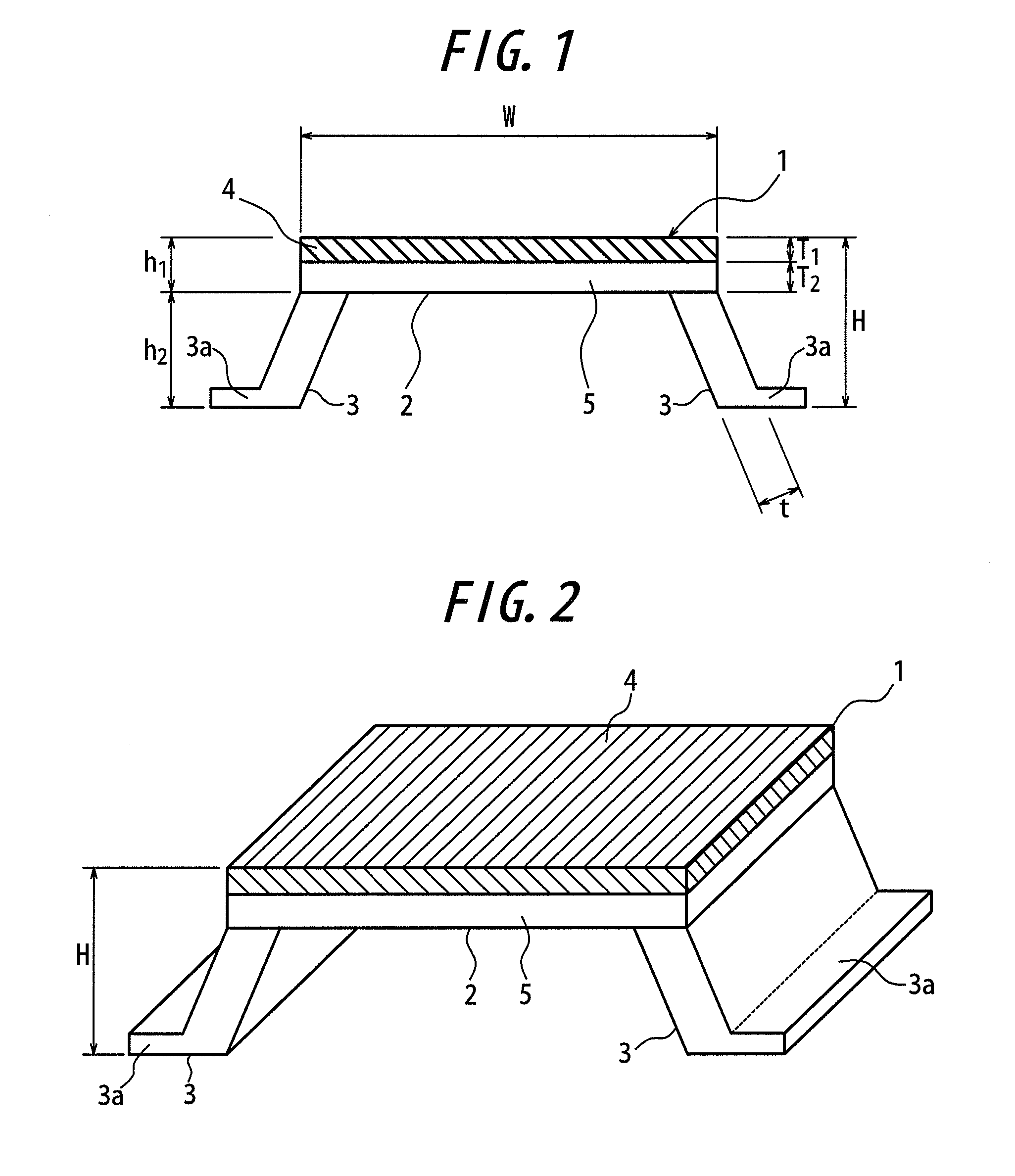
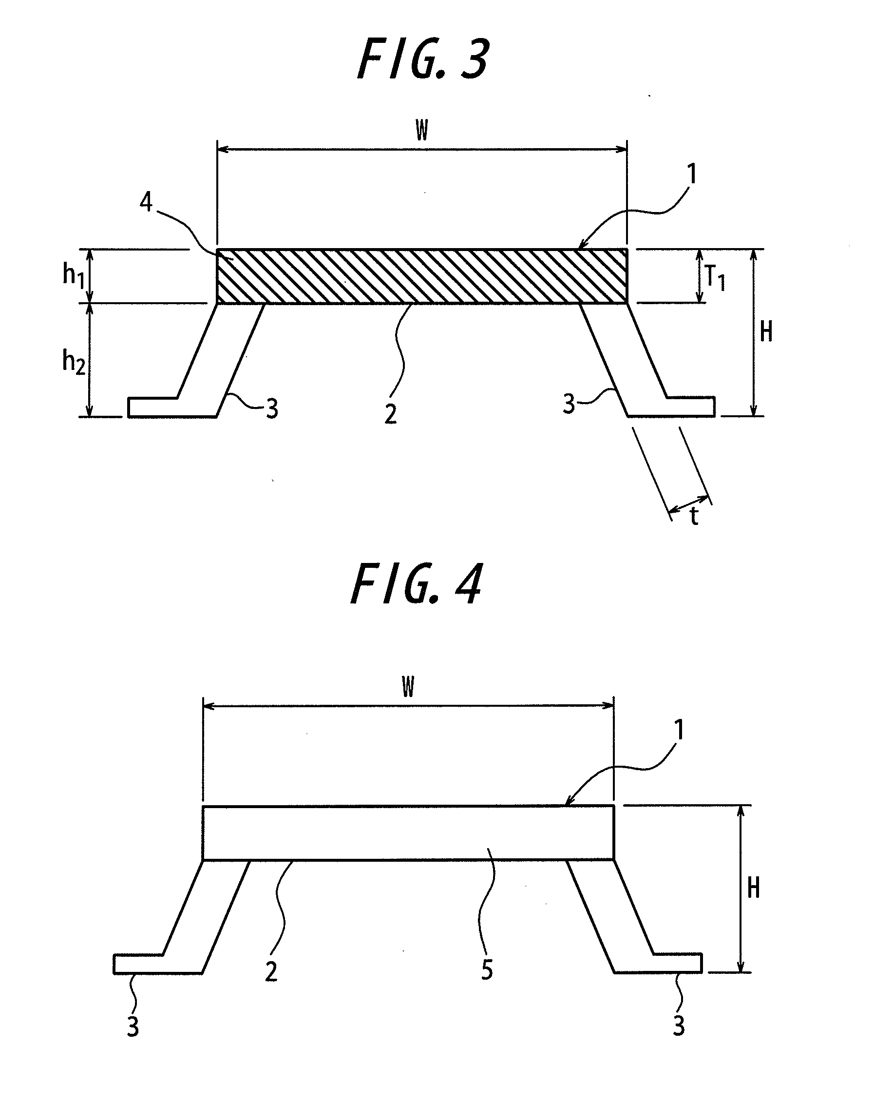
[0044]The invention will be described in detail with reference to the accompanying drawings. A marine fender 1 shown in FIGS. 1 and 2 comprises a shock receiving portion 2 receiving shock in the berthing of a marine vessel and a pair of leg portions 3 attached to a lower face of the shock receiving portion 2. At this moment, the leg portion 3 is made from rubber, and a flange 3a for fixing the fender 1 to a quay wall or the like is provided on the leg portion 3. The shock receiving portion 2 in FIGS. 1 and 2 comprises a shock receiving board 4 made from a resin at a face contacting with the vessel (i.e. outermost face), and a shock receiving board 5 made from rubber and disposed on the downside of the shock receiving resin board 4 in a height direction of the fender (or thickness direction of the shock receiving board). Moreover, the shock receiving portion in the marine fender of the invention is sufficient to at least comprise the shock receiving resin board 4. In the shock receiv...


PUM


Abstract

This invention relates to a marine fender being low and uniform in the compression surface pressure and excellent in the wear characteristics, and more particularly to a marine fender comprising a shock receiving portion 2 inclusive of a shock receiving resin board 4 and a pair of rubbery leg portions 3 disposed on the downside of the shock receiving portion 2 in a height direction of the fender, characterized in that a width W (mm) of the shock receiving portion 2 and a height H (mm) of the fender 1 satisfy a relation of the following equation (1);
2H≦W  (1)
and a thickness h1 (mm) of the shock receiving portion, a height h2 (mm) of the leg portion, a thickness t (mm) of the leg portion and a height H (mm) of the fender satisfy a relation of the following equation (2);
h2/4≦t≦h1≦H/2≦h2  (2).

Description

TECHNICAL FIELD[0001]This invention relates to a marine fender, and more particularly to a marine fender being low and uniform in the compression surface pressure and excellent in the wear characteristics, and further to a marine fender which is small in the deterioration of the resistance to compression load even if a shock receiving board is worn and easy in the replacement with a new shock receiving board.RELATED ART[0002]Heretofore, marine fenders are attached to quay wall for protecting the quay wall and marine vessels from shock and wear when the marine vessel is berthed to quay of harbor, river, vessel repairing dock or the like. As such a fender is common a rubbery fender. However, rubber is high in the friction coefficient with iron mainly constituting an outer surface of the vessel (usually 0.4) and is worn by rubbing, scratching, chipping or the like based on the behavior of the vessel in shear direction. On the other hand, there is known a marine fender wherein a shock r...

Claims


Application Information

Patent Timeline
Patent Type & Authority Applications(United States)
IPC IPC(8): E02B3/26
CPCE02B3/26Y02A30/30
Inventor YASUI, MOTOHIRO
Owner BRIDGESTONE CORP
Why Eureka
Try Eureka