Creasing Devices

a technology of creases and slits, applied in the field of creases, can solve the problems of poor quality stock, unsightly creases to the eye, rough touch, etc., and achieve the effect of sufficient resiliency, greater freedom of deformation, and no risk of damage to the stock

Active Publication Date: 2017-07-06
TECH NI FOLD LTD
View PDF15 Cites 0 Cited by
  • Summary
  • Abstract
  • Description
  • Claims
  • Application Information

AI Technical Summary

Benefits of technology

[0013]Optionally a further region of the outer surface that is not immediately adjacent to the lateral ribs is cylindrical, having a third radius that is larger than the first radius. In this embodiment the adjacent region of the outer surface is recessed relative to the further region of the outer surface. If the lateral ribs are formed of a resilient material, these adjacent recesses permit them greater freedom to deform laterally (i.e. in the direction along the axis) when the tips of the lateral ribs are compressed against the stock.
[0014]The material of the lateral ribs may be chosen to provide a sufficient degree of compression of the stock without the risk of damage to it. Given that the lateral ribs on the female side are acting (through the sheet) against the resilient shoulders of the creasing ring on the male side, there may be sufficient resiliency on the male side for the lateral ribs to be formed integrally with the remainder of the female drum and from the same rigid material, which is typically steel. However, forming the lateral ribs from a different material allows their material characteristics such as resilience, grip and durability to be chosen independently from those of the rest of the drum. If the ribs are not to be formed from the same material as the drum then they must be provided by one or more inserts. Provision must normally be made for replacement of the inserts when they have become worn and optionally also for exchanging the inserts to accommodate different types and thicknesses of stock or different styles of crease.
[0015]The pair of lateral ribs and the central channel may be formed by a single insert that is located in a single circumferential groove in the female drum. One suitable material for such an insert would be nylon, which provides good wear characteristics and can form a relatively rigid base of the central channel, while retaining a certain amount of resilience in the lateral ribs.

Problems solved by technology

When stock printed in this way is subsequently folded along a pre-formed crease, the coating has a tendency to crack and reveal the colour of the underlying stock, which can make the crease unsightly to the eye and rough to the touch.
The problem is particularly acute when poor quality stock, for example recycled card and paper, and poor quality inks are employed.

Method used


Image

  • Creasing Devices
  • Creasing Devices
  • Creasing Devices

Examples


Embodiment Construction

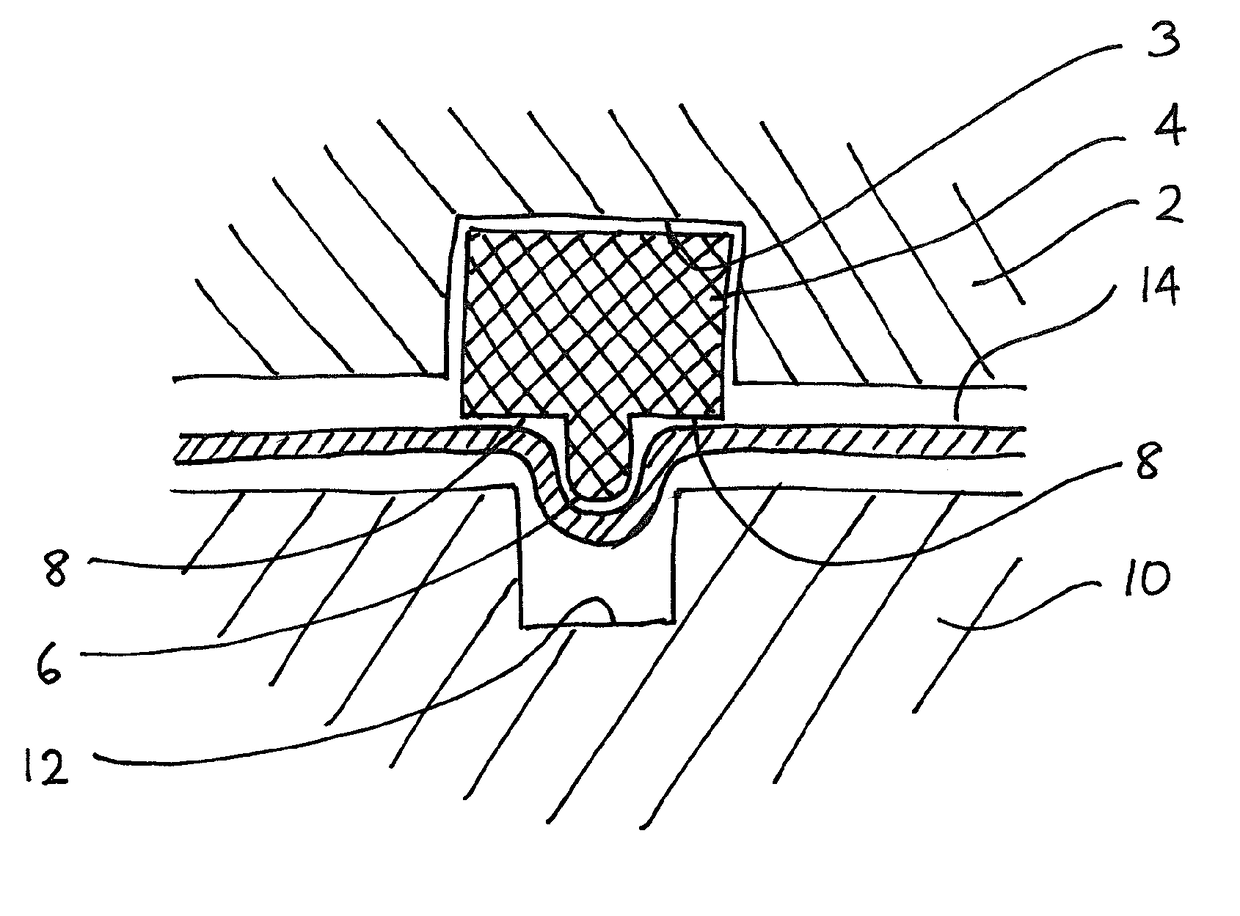
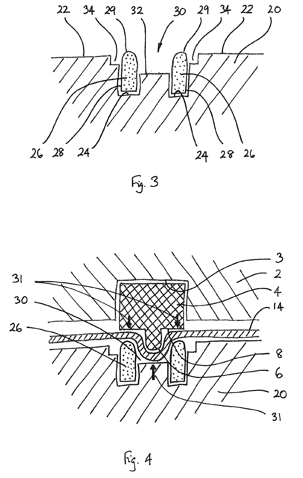
[0031]FIG. 3 shows a female drum 20 of a creasing device according to a first embodiment of the invention. FIG. 4 shows the creasing device comprising the female drum of FIG. 3 in use with a male drum 2 and creasing ring 4 that are the same as shown in FIG. 1. The female drum 20 comprises a cylindrical outer surface 22, in which are formed a pair of grooves 24 extending around the circumference of the drum 20. In each of the grooves 24 is mounted a rib 26 that projects from the mouth of the groove 24 beyond the radius of the cylindrical outer surface 22. The lateral ribs 26 define between them a circumferential central channel 30.

[0032]In use, the central channel 30 is aligned with the creasing rib 6 on the creasing ring 4 of the male drum 2. The spacing of the lateral ribs 26 of the female drum is such that they are respectively aligned with the shoulders 8 of the creasing ring 4 of the male drum 2. When the male and female drums 2,20 are counter-rotated and a sheet of the stock 14...


PUM


Abstract

A creasing device is provided that includes a counter-rotating male drum and female drum. The male drum carries a conventional creasing ring with a central rib flanked by shoulders. The female drum comprises a central channel aligned with the creasing rib on the male drum; and a pair of projecting lateral ribs on each side of the central channel that are aligned with the shoulders on the male drum. The lateral ribs press a sheet of the card or paper stock against the shoulders of the creasing ring to better define the edges of the crease and to reduce the tendency of a printed coating on the stock to crack during subsequent folding. The pair of lateral ribs may be provided by a pair of inserts. Alternatively, both ribs and the central channel may be provided by a single insert.

Description

CROSS-REFERENCE TO RELATED PATENT APPLICATIONS[0001]This patent application is continuation of International Application No. PCT / GB2015 / 052747, filed on Sep. 23, 2015, which claims priority to United Kingdom Application No. 1416770.4, filed on Sep. 23, 2014, the entire teachings and disclosure of which are incorporated herein by reference thereto.FIELD OF THE INVENTION[0002]This invention relates to creasing devices for creasing stock such as paper, card, film, foil or other sheet material to enable it to be easily folded. Such a device may be fitted to the output of a printing machine or the input of a folding machine or it can be used in a stand-alone creasing machine or in other contexts.BACKGROUND OF THE INVENTION[0003]A high percentage of printed stock such as book covers and brochures needs to be creased before the next operation of folding can be carried out. The substrate for the printing may be paper, card, film, foil or any other suitable sheet material.[0004]A known devic...

Claims


Application Information

Patent Timeline
Patent Type & Authority Applications(United States)
IPC IPC(8): B31F1/10B42C7/00
CPCB42C7/005B31F1/10B31F1/0006B31F5/022B31F1/0077B31F1/0003B31F1/07
Inventor HARRIS, GRAHAM MICHAEL
Owner TECH NI FOLD LTD
Why Eureka
Try Eureka