Reciprocating Compressor Wrist Pin Bearing and Lubrication Passageway

a compressor and wrist pin technology, applied in the direction of connecting rod bearings, liquid fuel engines, positive displacement liquid engines, etc., can solve the problems of inability to design on the basis of friction, small space inside the piston, and poor wear characteristics, so as to achieve better wear characteristics

Inactive Publication Date: 2012-03-22
CARRIER CORP
View PDF11 Cites 0 Cited by
  • Summary
  • Abstract
  • Description
  • Claims
  • Application Information

AI Technical Summary

Benefits of technology

[0011]Improved compressors are disclosed that provide better wear characteristics for wrist pins and connecting rods of reciprocating compressors with small pistons, such as reciprocating compressors for higher pressure working fluids like CO2.

Problems solved by technology

A good deal of friction is encountered in these connecting rod bearings from transmitting the force of actuation to the piston.
The space inside the piston is also small which inhibits designs relying upon splash-feed lubrication to the wrist pin.
Because of the problems associated with getting lubricant delivered to the wrist pin, the typical materials such as aluminum for the connecting rod and steel for the wrist pin are not sufficiently reliable.
U.S. Pat. No. 7,128,528 discloses a two-stage CO2 compressor and a scroll-type CO2 compressor that relies upon special materials for its bearings, such as graphite, but does not address the problems associated with stress on wrist pins and delivering lubricant to wrist pins of reciprocating CO2 compressors or similar reciprocating compressors.
However, this design does not permit inclusion of a bearing surrounding the wrist pin and therefore does not completely address the problem of premature wear or failure of a steel wrist pin.

Method used


Image

  • Reciprocating Compressor Wrist Pin Bearing and Lubrication Passageway
  • Reciprocating Compressor Wrist Pin Bearing and Lubrication Passageway
  • Reciprocating Compressor Wrist Pin Bearing and Lubrication Passageway

Examples


Embodiment Construction

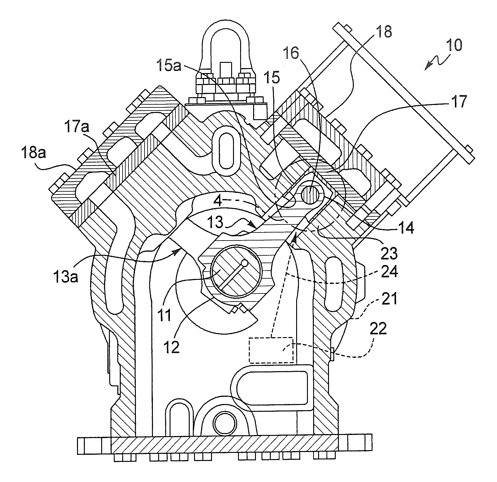
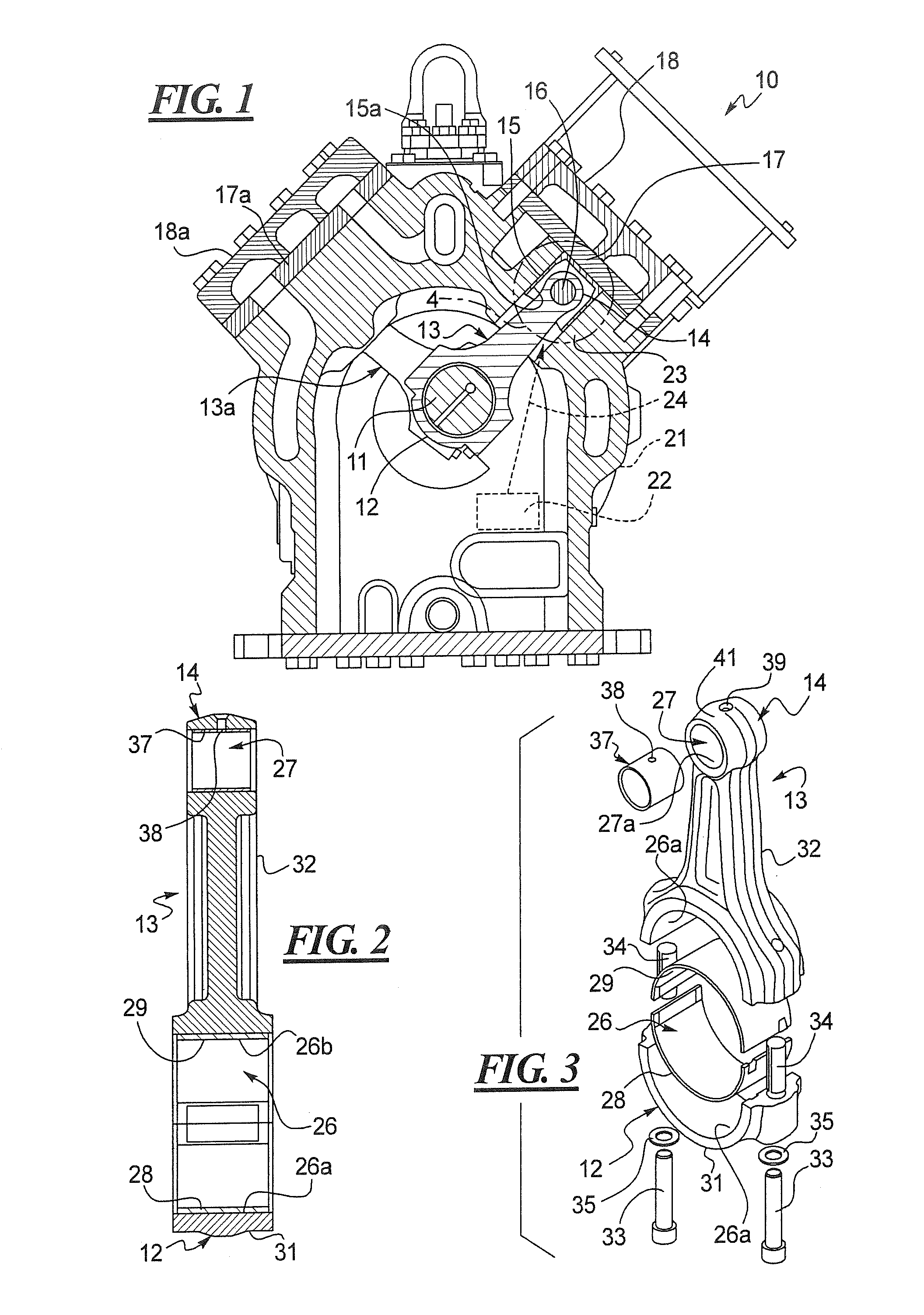
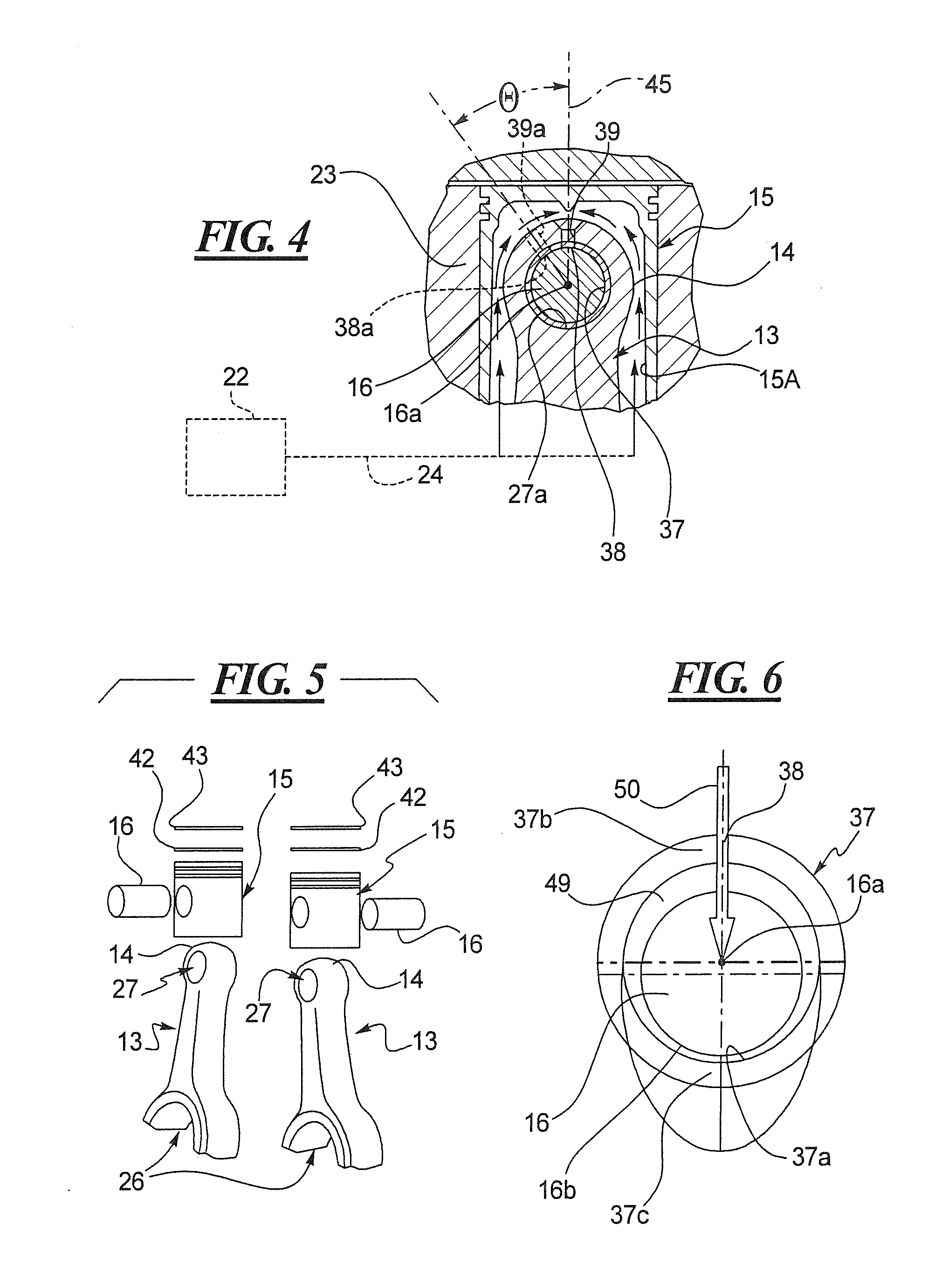
[0023]A compressor 10 is illustrated in FIG. 1 with a motor (not shown) that drives the crankshaft (not shown) that rotates the eccentric 11 received within the proximal ends 12 of the connecting rod 13. The connecting rod 13 includes a distal end 14 that is connected to a piston 15 by a wrist pin 16, as best seen in FIGS. 4-5. While only a single connecting rod 13 is illustrated in FIG. 1, compressors such as those shown at 10 in FIG. 1 typically include four connecting rods 13 or two pairs of connecting rods 13, one such pair of parallel connecting rods 13 being illustrated in FIG. 5. Another connecting rod 13a is also illustrated in FIG. 1 and is disposed in a parallel relationship with an additional connecting rod 13a (not shown). The connecting rods 13, 13a may be fabricated from aluminum, an aluminum alloy, various steels, cast irons or magnesium alloys.

[0024]The pistons 15 shown in FIGS. 1 and 5 move towards and away from the valve plate 17 and head 18 to compress a gas, such...


PUM


Abstract

A compressor, as well as a lightweight and strong casting for a compressor, are disclosed. The compressor, which may be a reciprocating compressor for use in compressing high-pressure refrigerants such as CO2, includes substantially reduced wall thicknesses (t) compared to prior art castings. The side walls of the compressor can be manufactured to such reduced thicknesses (t) through the use of a bridge spanning across the crankcase. This not only allows the opposing side walls to be manufactured of a thinner material, but the bottom cover removably mounted to the crankcase can be manufactured from a thinner and lighter material as well. Through the use of such a bridge, the resulting compressor is not only able to satisfy current strength requirements, but at significant weight, size and cost savings as well.

Description

CROSS-REFERENCE TO RELATED APPLICATION[0001]This is a non-provisional patent application claiming priority under 35 USC §119(e) to U.S. Provisional Patent Application Ser. No. 61 / 181,929 filed on May 28, 2009.BACKGROUND[0002]1. Technical Field[0003]This disclosure relates to reciprocating compressors and, more specifically, to reciprocating compressors suitable for use with carbon dioxide refrigerant. Still more specifically, this disclosure relates to an improved connecting rod / wrist pin design for more reliable operation of such reciprocating compressors.[0004]2. Description of the Related Art[0005]Compressors are utilized in many applications to compress various fluids. One type of compressor is a reciprocating piston compressor. In a reciprocating piston compressor, a crankshaft rotates at least one eccentric. Each eccentric in turn drives a connecting rod that is connected to a piston by a wrist pin. The connecting rod typically includes a larger proximal end lined with a beari...

Claims


Application Information

Patent Timeline
Patent Type & Authority Applications(United States)
IPC IPC(8): F04B39/12
CPCF04B39/121F04B53/147F04B53/18F16C33/16F16C33/10F16C33/12F16C9/04F16C2204/20F16C33/122F16C2204/60
Inventor FLANIGAN, PAUL J.
Owner CARRIER CORP
Why Eureka
Try Eureka