
Electronic sphygmomanometer

a sphygmomanometer and electronic technology, applied in the field of sphygmomanometer, can solve the problems of user concern, abnormality detection, and inability to determine whether the blood pressure measurement value is correct,

Inactive Publication Date: 2012-08-09
OMRON HEALTHCARE CO LTD
View PDF5 Cites 15 Cited by
  • Summary
  • Abstract
  • Description
  • Claims
  • Application Information

AI Technical Summary

Benefits of technology

[0009]In view of this, one or more embodiments of the present invention provide an electronic sphygmomanometer that can improve the reliability of blood pressure measurement values in blood pressure measurement that employs multiple pressure sensors.
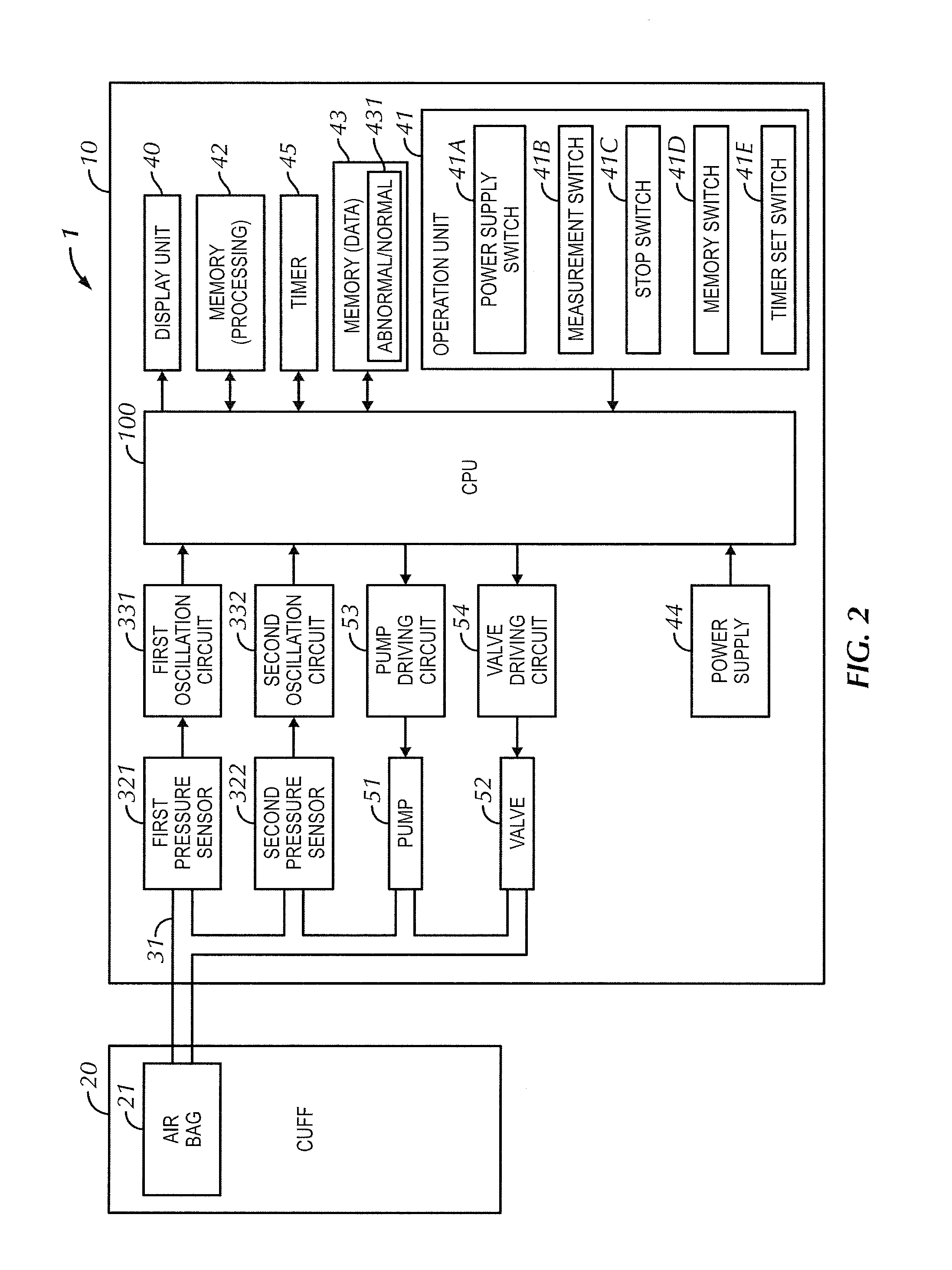
[0025]According to one or more embodiments of the present invention, in the process of blood pressure measurement performed based on cuff pressures detected using multiple pressure sensors, abnormality detection is performed with respect to at least one of the pressure sensors based on pressure information that was detected while the cuff pressures were held at a predetermined pressure. This enables performing accurate abnormality detection.

Problems solved by technology

For this reason, even if the pressure sensor output, which is of utmost importance in blood pressure measurement, deviates beyond the specified tolerance margin, there is no way to know that this has happened, and therefore it is not clear whether blood pressure measurement values are correct.
Also, even if there is a large difference between a blood pressure measurement value and the normal blood pressure measurement value or the casual blood pressure measurement value, it is not clear whether the actual blood pressure values are different, or the blood pressure values are different due to error in the pressure sensor of the sphygmomanometer, thus causing the user to become concerned.
Specifically, an abnormality is detected if the pressure value detected by the second pressure sensor greatly exceeds 300 mmHg, for example.
Accordingly, the second pressure sensor is applied as a safety measure specified in the medical standard IEC 60601-2-30, and does not guarantee the precision of the first pressure sensor used for blood pressure measurement.

Method used


Image

  • Electronic sphygmomanometer
  • Electronic sphygmomanometer
  • Electronic sphygmomanometer

Examples


examples

[0149]Display Examples

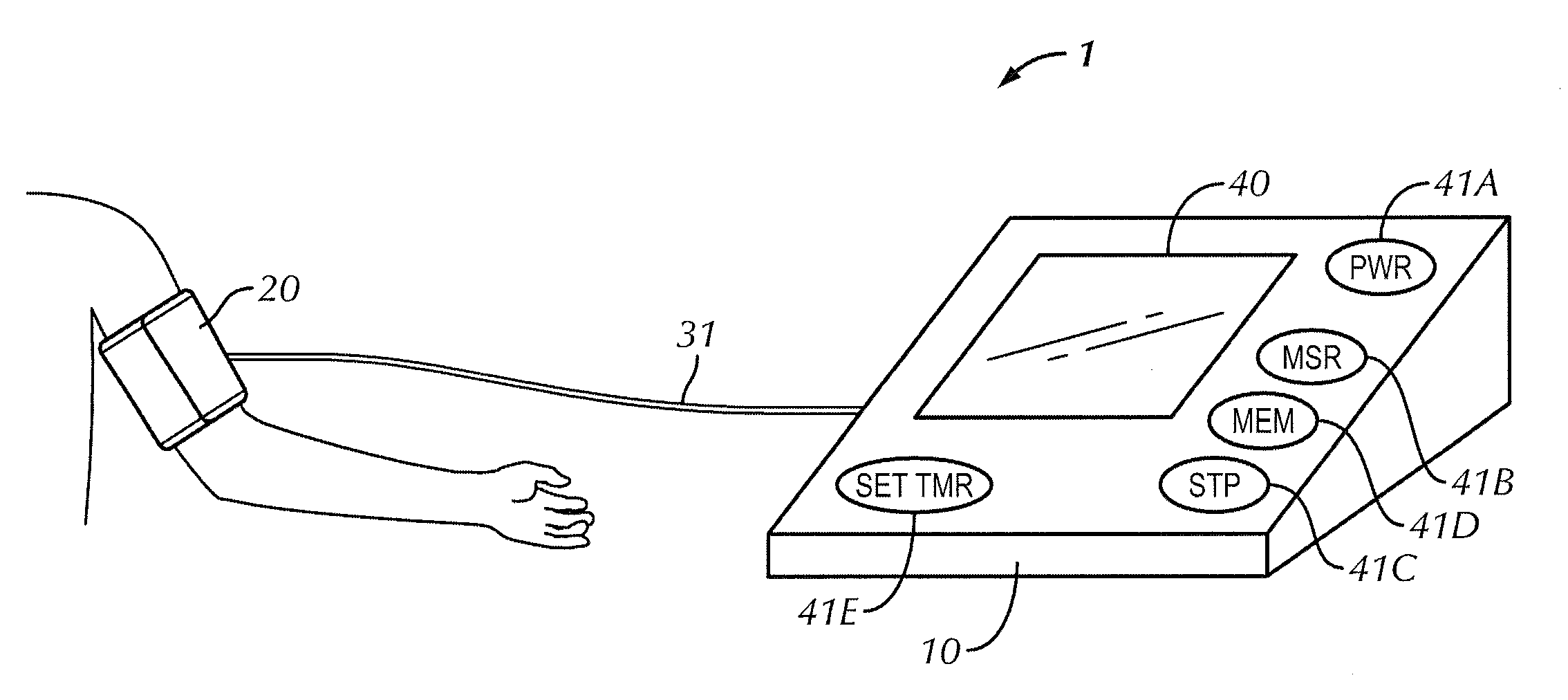
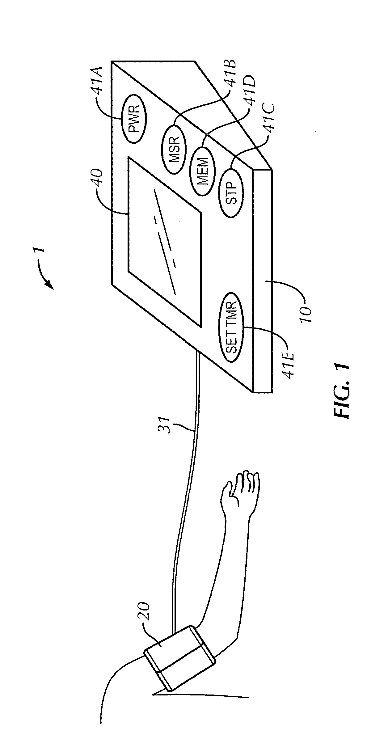
[0150]FIG. 16 shows an example of the display of pressure sensor abnormality detection results on the display unit 40. Although calculated blood pressure values are not stored in the memory 43 in the case where a pressure sensor abnormality has been detected in the flowcharts described above, the calculated blood pressure values may be stored in association with the abnormality detection result. In this case, the pressure sensor abnormality detection result is displayed along with the display of the blood pressure measurement values.

[0151]In FIG. 16, the display processing unit 115 switches the display mode based on the detection result of the sensor abnormality detection unit 113. Specifically, if the first and second pressure sensors 321 and 322 are operating normally, the display of the characters “ERR” is switched off, and only the display of the characters “OK” is switched on. If the detection result indicates that an abnormality occurred, the display of t...


PUM


Abstract

An electronic sphygmomanometer includes a cuff that can be worn at a measurement site, a pressure adjustment unit that adjusts the pressure applied inside the cuff; a pressure detection unit that includes multiple pressure sensors and that detects the cuff pressure inside the cuff based on pressure information output from the pressure sensors, a blood pressure calculation unit that calculates a blood pressure based on change in the cuff pressure detected by the pressure detection unit during blood pressure measurement, a keeping unit that keeps the cuff pressure at a predetermined pressure using the pressure adjustment unit during blood pressure measurement, and a sensor abnormality detection unit that, in a state in which the keeping unit keeps the cuff pressure at the predetermined pressure, detects whether an abnormality has occurred in the pressure sensors based on the pressure information output from the pressure sensors.

Description

TECHNICAL FIELD[0001]The present invention relates to an electronic sphygmomanometer, and in particular to an electronic sphygmomanometer that improves the reliability of blood pressure measurement values.BACKGROUND ART[0002]Blood pressure is one index for analyzing cardiovascular disease. Performing a cardiovascular disease risk analysis based on blood pressure is effective in preventing cardiovascular-related conditions such as stroke, heart failure, and myocardial infarction. In particular, early-morning hypertension; in which the blood pressure rises in the early morning, is related to heart disease, stroke, and the like. Among early-morning hypertension symptoms, the symptom called “morning surge”, in which the blood pressure rapidly rises within one hour to one and a half hours after waking up, has been found to have a causal relationship with stroke. In view of this, understanding the interrelationship between time (lifestyle) and changes in blood pressure is useful in risk a...

Claims


Application Information

Patent Timeline
IPC IPC(8): A61B5/022
CPCA61B5/02225A61B5/0225A61B2562/0247A61B5/6824A61B5/024
Inventor YAMASHITA, SHINGOSAWANOI, YUKIYA
Owner OMRON HEALTHCARE CO LTD
Learn More