Device and method for temporary or permanent suspension of an implantable scaffolding containing an orifice for placement of a prosthetic or bio-prosthetic valve

a technology of bioprosthetic valves and scaffolding, which is applied in the field of medical devices and procedures, can solve the problems of limited pathological state benefits of these advances, and achieve the effect of minimal delivery system siz

Inactive Publication Date: 2012-08-09
ANNEST LON SUTHERLAND
View PDF7 Cites 193 Cited by
  • Summary
  • Abstract
  • Description
  • Claims
  • Application Information

AI Technical Summary

Benefits of technology

[0053]It is possible that after restriction / capture of the valve leaflets, the neo-annulus / captured valve contact will not completely eliminate leakage around the valve. In one embodiment of an implantation system in accordance with the invention, an inflatable or otherwise expandable component such as an annular bladder can be enlarged around the neo-annulus to further inhibit paravalvular leak and enhance the seal between the native valve and the scaffold / replacement valve. This sealing component may initially take the form of a collapsed inner-tube-like component that is attached to the neo-annulus or that is separately delivered and positioned in situ. The inflatable sealing component is provided with an inflation tube through which air, saline solution, another fluid, or other appropriate substance, such as polymers, is infused, expanding the sealing component to eliminate potential or actual peri-valvular leak. After expansion of the sealing component, the inflation tube is removed / plugged, or otherwise eliminated from permanent connection with the inflatable sealing component. Also, a fluid, such as saline, may be initially infused, but later be exchanged for another, potentially permanent material, such as a polymer or other material of appropriate properties.
[0104]The present invention contemplates a leaflet capture device with hooks, barbs, or other appropriate components that grasp and entrain the valve leaflet edges and curl the leaflets against the replacement valve annulus or scaffold margin, thereby retracting and disabling the leaflets around the margin of the replacement valve or into the scaffold. This procedure has the additional benefit of sealing the edge or margin of the scaffold against leakage. The bunched up leaflets serve as a “gasket” against leakage of blood back into the atrium, thereby making discontinuous attachment to the heart or blood vessel wall of the scaffold margin to the atrial wall feasible from a standpoint of valvular or peri-valvular regurgitation.

Problems solved by technology

Consequently, the benefit of these advances is limited to specific pathological states.

Method used


Image

  • Device and method for temporary or permanent suspension of an implantable scaffolding containing an orifice for placement of a prosthetic or bio-prosthetic valve
  • Device and method for temporary or permanent suspension of an implantable scaffolding containing an orifice for placement of a prosthetic or bio-prosthetic valve
  • Device and method for temporary or permanent suspension of an implantable scaffolding containing an orifice for placement of a prosthetic or bio-prosthetic valve

Examples


Embodiment Construction

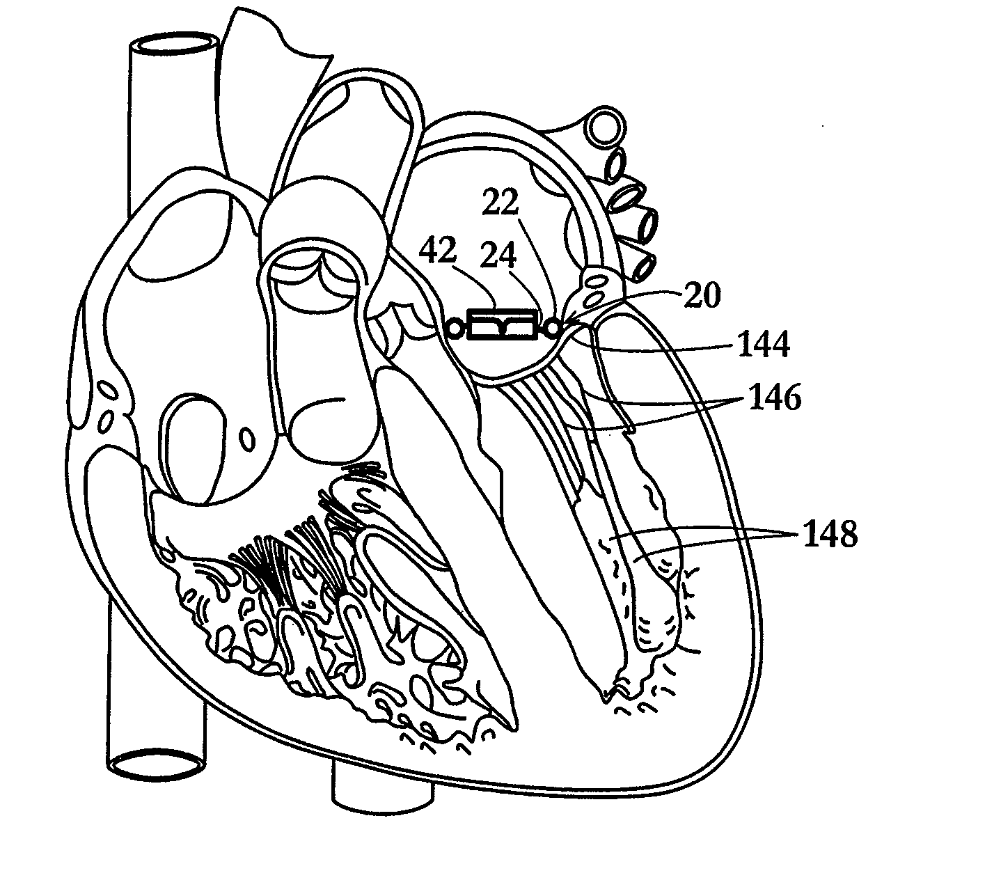
[0227]The present invention provides devices and associated methodology for attaching a valve-supporting scaffold or frame member to a subject, particularly to natural valve leaflets of a native heart or vessel valve of the subject. Such a valve-supporting scaffold and methods related thereto are disclosed in U.S. Patent Application Publication No. 2010 / 0262232, the disclosure of which is hereby incorporated by reference.

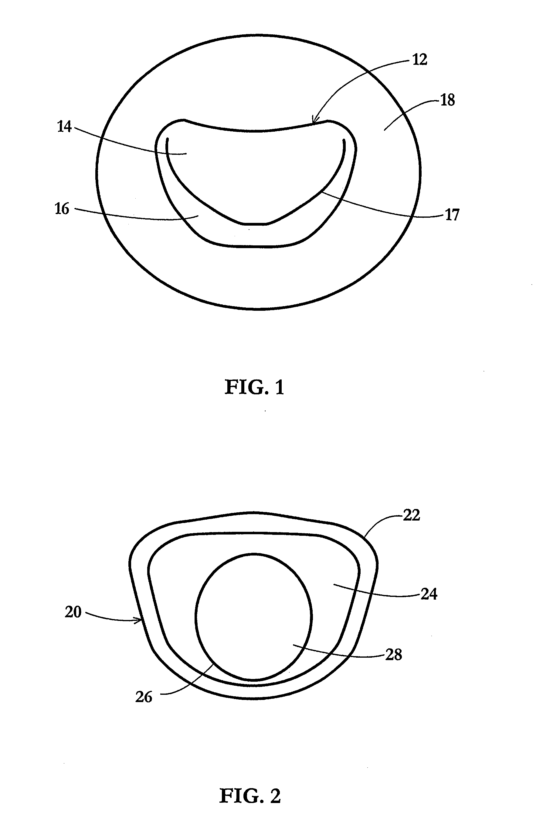
[0228]As depicted in FIG. 1, a mitral valve 12 includes a pair of leaflets or valve flaps 14 and 16 that contact one another along a generally D-shaped set of points 17 in a closed state of the valve. On the atrial side of the valve 12, leaflets are continuous with an internal wall 18 of the atrium.

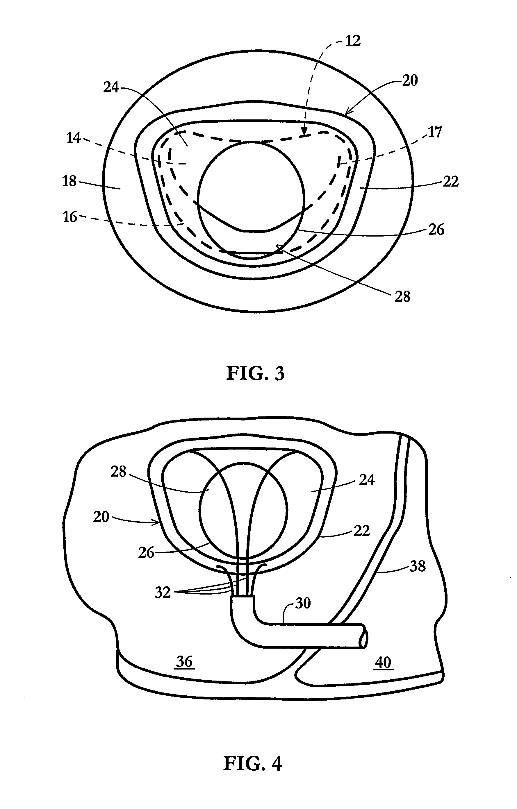
[0229]As depicted in FIG. 2, an implantable valve scaffold or mounting component 20 includes an outer margin or rim element 22, a membranous portion 24, and a generally annular inner margin or rim element 26 defining an orifice 28. Orifice 28 serves as a neo-annulus for r...


PUM


Abstract

In a surgical method for improving cardiac function, an implantable scaffold Or valve support device is inserted inside a patient's heart and attached to the heart in a region adjacent to a natural mitral or other heart valve. The scaffold or valve support device defines an orifice and, after the attaching of the scaffold or valve support device to the heart, or temporary support while native valve leaflets and / or subvalvular structures are captured, a prosthetic or bio-prosthetic valve seated in the orifice, and the native valve may be retracted into the scaffold / replacement assembly to create a gasket for sealing the complex.

Description

CROSS-REFERENCE TO RELATED APPLICATIONS[0001]This application is a continuation-in-part of U.S. patent application Ser. No. 12 / 798,629 filed Apr. 8, 2010 and claiming the benefit of U.S. Provisional Patent Application No. 61 / 168,279 filed Apr. 10, 2009. This application also claims the benefit of U.S. Provisional Patent Application No. 61 / 439,734 filed Feb. 4, 2011 and the benefit of U.S. Provisional Patent Application No. 61 / 518,772 filed May 11, 2011.FIELD OF THE INVENTION[0002]The present invention relates to medical devices and procedures, in particular related to the fixation within the heart or blood vessel of a device which enables replacement of a heart valve, and more particularly, to a novel device for use in a novel procedure for performing a catheter-based heart valve replacement.BACKGROUND OF THE INVENTION[0003]The four valves of the human heart consist of either two or three pliable leaflets attached circumferentially to a fibrous skeletal annulus. Normally, heart valv...

Claims


Application Information

Patent Timeline
Patent Type & Authority Applications(United States)
IPC IPC(8): A61F2/24
CPCA61F2/246A61F2/2409A61B17/0469A61B2017/003A61B2017/0441A61F2/2412A61B2017/00243A61B2017/0409A61B2017/00349A61F2250/0003A61F2250/006A61F2/2436A61B2017/0427A61F2220/0016A61F2/2457A61F2/2427A61F2/2439A61F2220/0008A61F2250/0006A61F2/2418A61F2/2445A61F2/2466
Inventor ANNEST, LON SUTHERLAND
Owner ANNEST LON SUTHERLAND
Why Eureka
Try Eureka