Circumferential Weld Scanner With Axial Drift Prevention

a circumferential weld scanner and axial drift technology, applied in the direction of instruments, measurement devices, specific gravity measurement, etc., can solve the problems of affecting the precision of inspection, axial drift significantly increases the risk of missing defects in regions, and already affects the accuracy of inspection, so as to prevent axial drift

Inactive Publication Date: 2012-08-16
GE HITACHI NUCLEAR ENERGY AMERICAS
View PDF2 Cites 55 Cited by
  • Summary
  • Abstract
  • Description
  • Claims
  • Application Information

AI Technical Summary

Benefits of technology

[0010]Yet another embodiment is method for preventing axial drift while inspecting a circumferential weld in a cylindrical conduit using an ultrasonic scanner. The method includes fixedly extending a guide track around the conduit adjacent to the weld, rotatably mounting the ultrasonic scanning apparatus to the surface of the conduit and coupling the guide track and the ultrasonic scanning apparatus such that the guide track is configured to limit axial displacement of the ultrasonic scanning apparatus during rotation of the ultrasonic scanning apparatus around the conduit.

Problems solved by technology

The inspection cannot be thorough and precise if the apparatus drifts axially so as to uncontrollably spiral or shift as it rotates around the pipe.
In fact, even if the scanning apparatus is designed to follow a helical path, axial drift significantly increases the risk of missing defects in regions that escape inspection.
However, detection of drift necessarily means that the drift has occurred, so the resulting inaccuracy has already impacted the precision of the inspection.
However, riding above the surface of the conduit on the external track elevates the profile of the scanning apparatus, which limits its ability to operate in areas with limited clearance.
An extended arm often fails to maintain stable and consistent contact or proximity between the scanning apparatus and the conduit, particularly when scanning the underside of a conduit, which results in hysteresis.
Achieving the desired level of precision is especially difficult when inspecting a tapered pipe that has diameters that vary along its length, or when using the same apparatus to inspect different various diameter pipes.

Method used


Image

  • Circumferential Weld Scanner With Axial Drift Prevention
  • Circumferential Weld Scanner With Axial Drift Prevention
  • Circumferential Weld Scanner With Axial Drift Prevention

Examples


Embodiment Construction

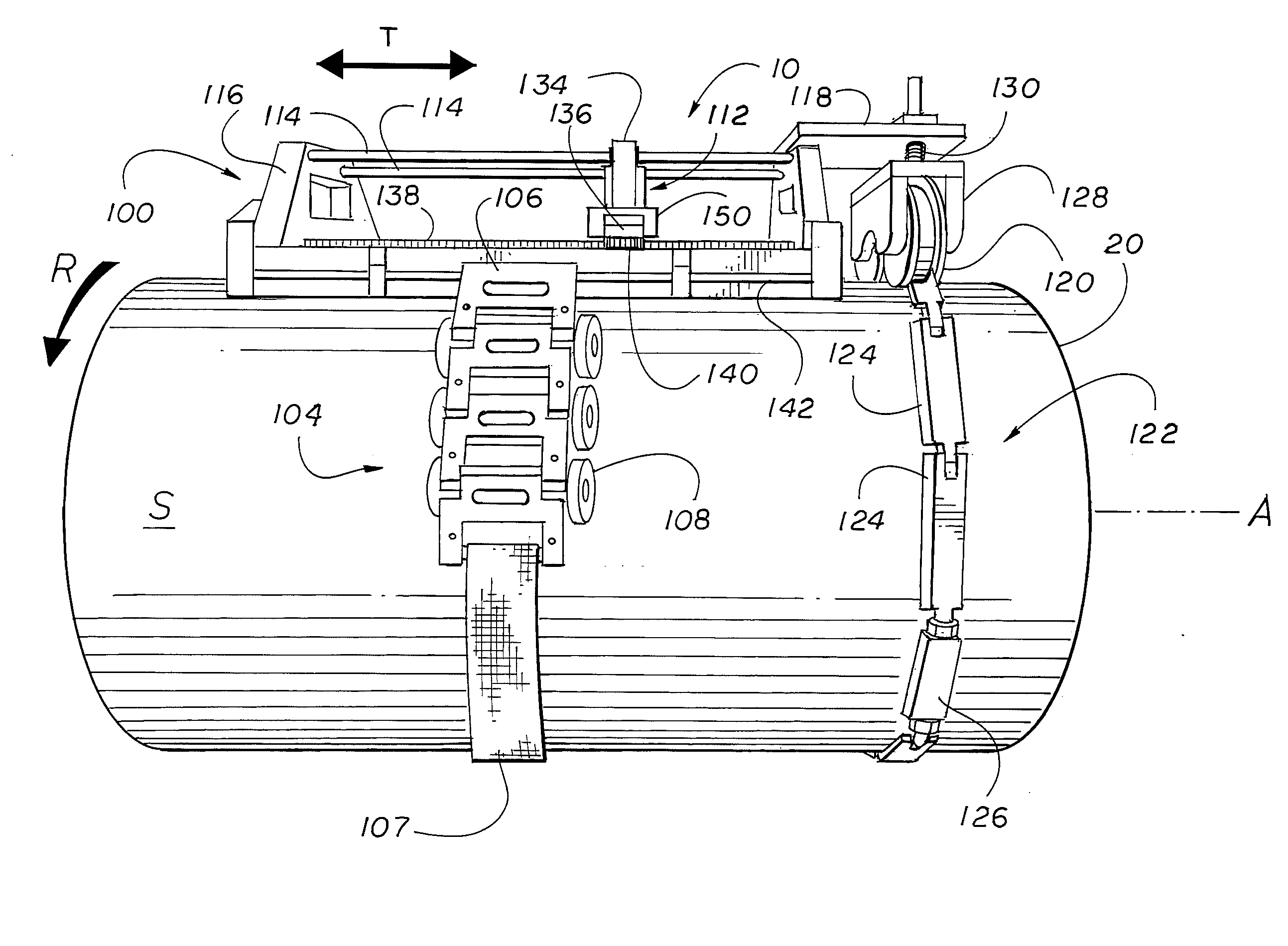
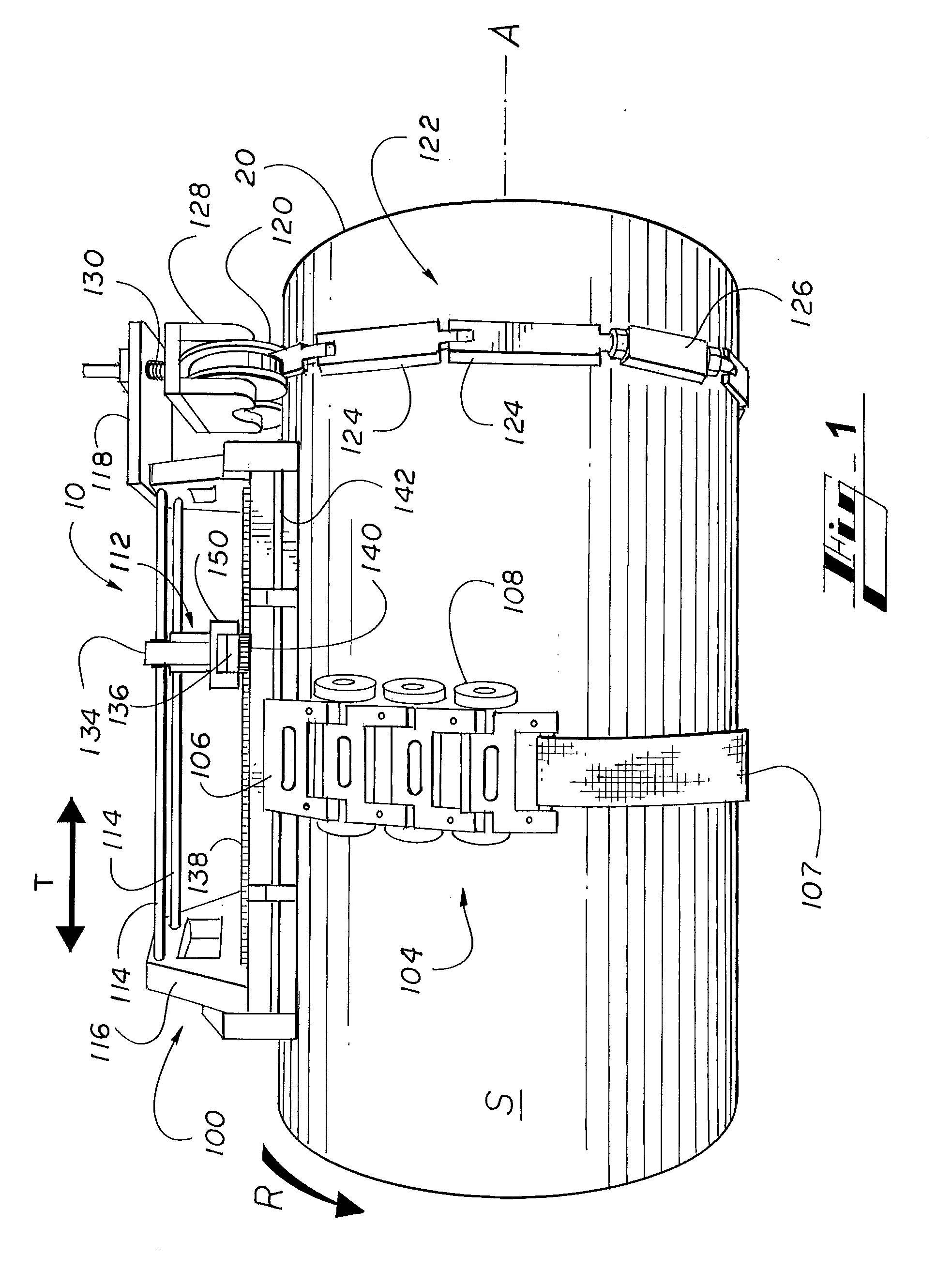
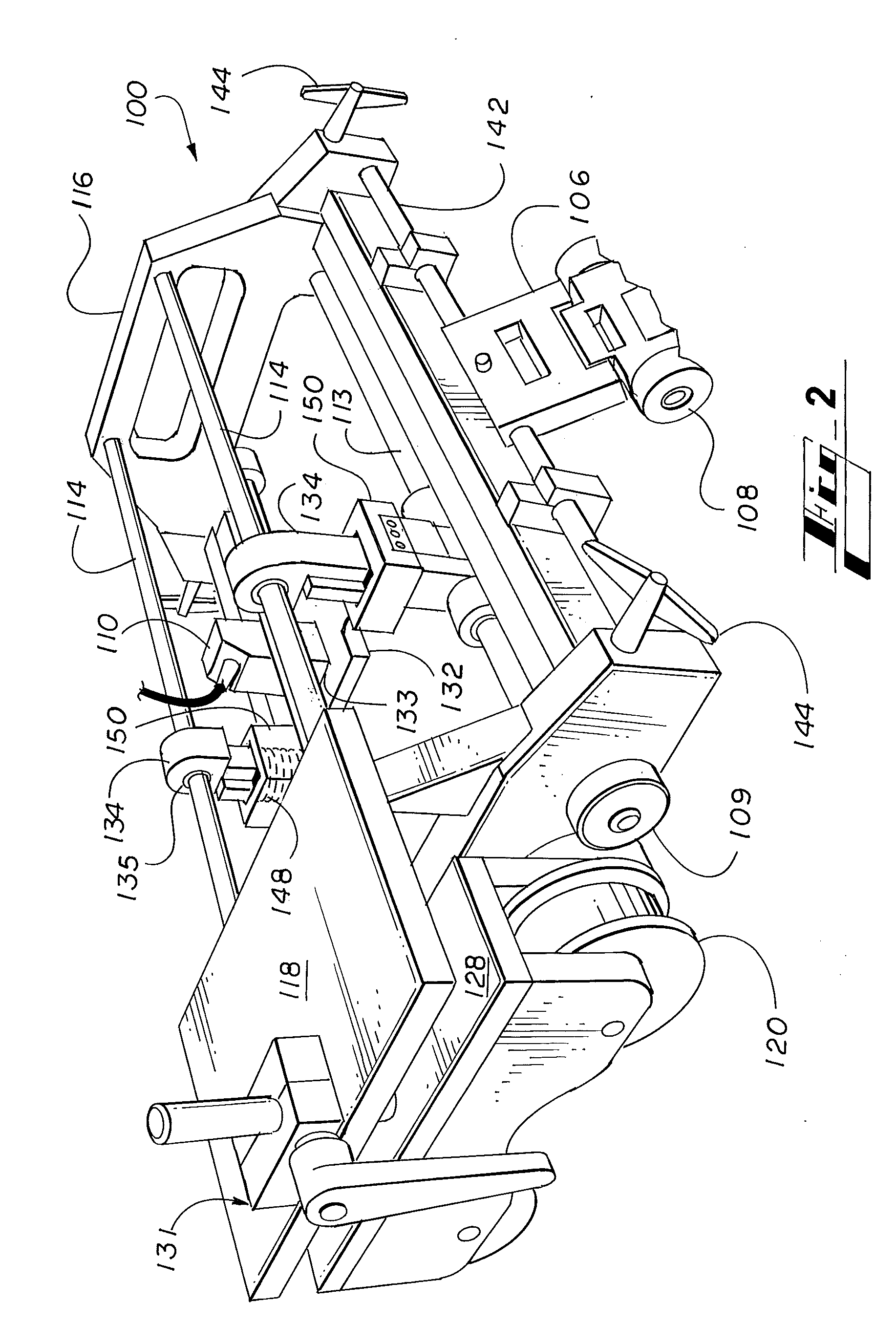
[0016]As required, detailed embodiments are disclosed herein. It must be understood that the disclosed embodiments are merely exemplary of and may be embodied in various and alternative forms, and combinations thereof. As used herein, the word “exemplary” is used expansively to refer to embodiments that serve as illustrations, specimens, models, or patterns. The figures are not necessarily to scale and some features may be exaggerated or minimized to show details of particular components. In other instances, well-known components, systems, materials, or methods that are known to those having ordinary skill in the art have not been described in detail in order to avoid obscuring the present disclosure. Therefore, specific structural and functional details disclosed herein are not to be interpreted as limiting, but merely as a basis for the claims and as a representative basis for teaching one skilled in the art.

[0017]An exemplary environment for implementing the various embodiments o...


PUM

PropertyMeasurementUnit
ultrasonic scanningaaaaaaaaaa
circumferenceaaaaaaaaaa
forceaaaaaaaaaa

Abstract

Inspection of circumferential sections of pipe or other conduit using an ultrasonic scanning apparatus is provided, wherein axial drift of the ultrasonic scanning apparatus is prevented using a guide track assembly. The guide track assembly is rigidly coupled to the ultrasonic scanning apparatus in the axial direction, but allows rotational motion of the ultrasonic scanning apparatus directly along the outer surface of the conduit using a drive chain that is driven by a circumferential drive. Secure rotational motion without drift between the guide track assembly and the ultrasonic scanning apparatus is maintained by the rigid coupling and by a spring-loaded wheel housing assembly that maintains contact of wheels that travel along the guide track. The ultrasonic scanning apparatus includes a transducer with spring-loaded gimbaling that maintains optimal proximity with the conduit surface. The transducer is translated axially along linear journals that extend along the conduit with a linear actuator.

Description

TECHNICAL FIELD[0001]The present invention relates generally to nuclear reactors, and more particularly, to devices for inspection of circumferential welds within a nuclear reactor pressure vessel.BACKGROUND OF THE INVENTION[0002]Typical protocols call for inspection of welds within a nuclear reactor during scheduled outages. Inspection devices are used to scan the welds to detect intergranular stress corrosion cracking (IGSCC), which has been known to occur for example, in connection with primary system piping dissimilar metal (DM) welds.[0003]Circumferential welds extend around the periphery of cylindrical conduits, such as the pipes and tubes commonly found in a reactor system. These welds may be inspected by positioning a scanning apparatus proximate to an outer surface of a pipe adjacent to the location of a weld, and rotating the scanning apparatus about the circumference of the pipe to inspect the entire extent of the weld. The inspection cannot be thorough and precise if the...

Claims


Application Information

Patent Timeline
Patent Type & Authority Applications(United States)
IPC IPC(8): G01N29/04
CPCG01N29/043G01N2291/2634G01N29/265
Inventor CRUMPTON, THOMAS H.MERCIER, EDMUND S.
Owner GE HITACHI NUCLEAR ENERGY AMERICAS
Why Eureka
Try Eureka