Harmonic motor, drive assembly, industrial robot, robot boom and robot joint

a drive assembly and motor technology, applied in the field of motors, can solve the problems of unsatisfactory robotics requirements, low torque characteristics, and high speed of prior art motors, and achieve the effects of reducing length, weight and cost, and simplifying the drive assembly

Inactive Publication Date: 2012-08-16
ABB RES LTD
View PDF7 Cites 22 Cited by
  • Summary
  • Abstract
  • Description
  • Claims
  • Application Information

AI Technical Summary

Benefits of technology

[0038]While the groove ball bearing may be a single row groove ball bearing, in another embodiment, the rear bearing is a spherical double-row groove ball bearing. Such a double row bearing may allow for smooth running under relative large axial misalignments.
[0039]While the strain wave gearing may conventionally be mounted to the drive end plate of the motor, in another embodiment o

Problems solved by technology

However, their high speed, low torque characteristics are not ideal for robotics axes in which high torque, low speed characteristics are desirable.
The prior art motors do not fulfill this need.
The concentricity demand for these parts is typically in the range of 10-20 μm and is very hard to meet in practice, since it requires strict tolerances on both the motor and the mounting surface for the motor.
If the wave generator concentric

Method used


Image

  • Harmonic motor, drive assembly, industrial robot, robot boom and robot joint
  • Harmonic motor, drive assembly, industrial robot, robot boom and robot joint
  • Harmonic motor, drive assembly, industrial robot, robot boom and robot joint

Examples


Embodiment Construction

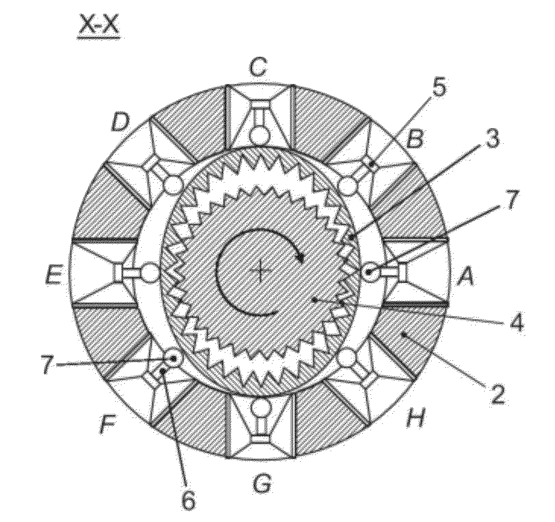
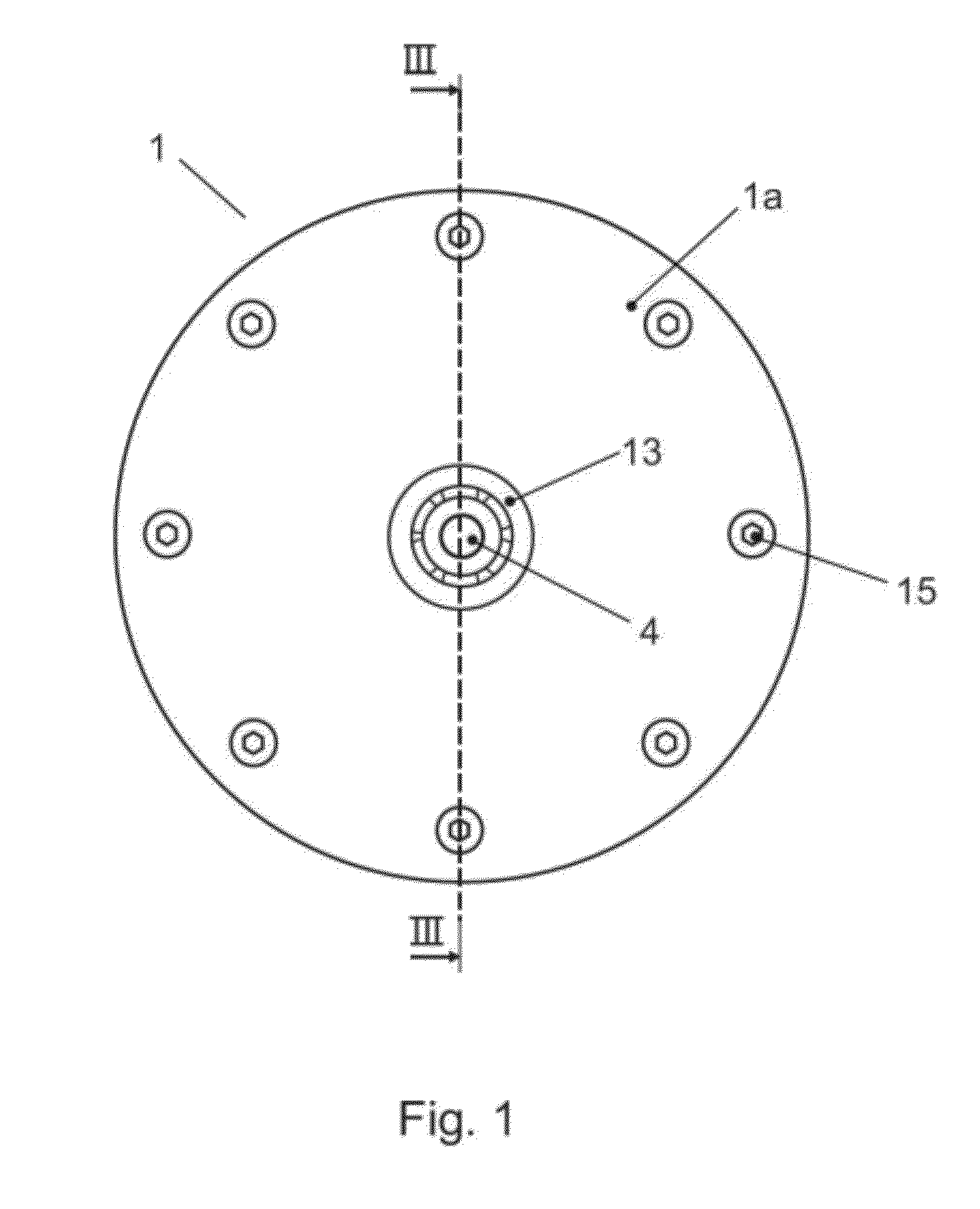
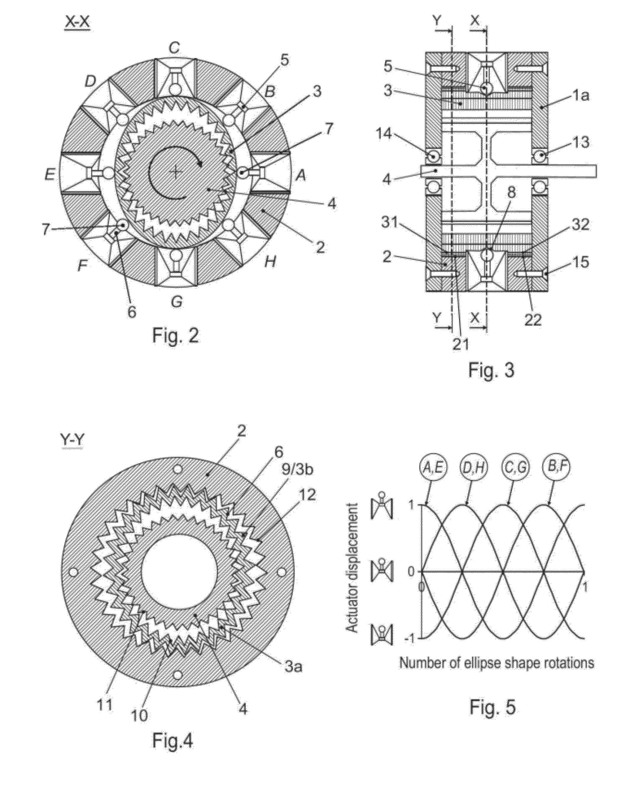
[0059]FIG. 1 is a harmonic motor 1 according to the present invention, where the housing 1a comprises fastening means 15 e.g. bolts. The motor comprises a fixed circular stator 2, a flex spline 3 and an output gear 4 (FIG. 2). The flex spline 3 is arranged coaxially within the stator 2. The output gear 4 is arranged coaxially within the flex spline 3 and supported by two bearings 13, 14 arranged in the housing 1a of the motor at a distance and on either side of the flex spline. Eight linear actuators 5 are mounted radially disposed on the internal surface 2a of the fixed stator 2. Each actuator comprises a means transferring force to the flex spline with an output shaft 6 connected to a ball 7. The ball is the rolling element within a miniature ball transfer unit.

[0060]The balls 7 locate in a v-shaped groove 8 arranged running around the central portion of the outer surface of the flex spline 3 (FIG. 3). The portions 31 and 32 on the outer surface 3b of the flex spline, flanking eit...


PUM


Abstract

A harmonic motor with a circular and internally geared stator, a flex spline coaxially arranged within the stator which comprises both external and internal gears, and a geared output shaft coaxially arranged within the flex spline. A drive assembly that includes a motor with a motor housing, a rotor, a rotor shaft, and a rear bearing for supporting the rotor shaft in the motor housing at a rear side of the rotor; and a strain wave gearing including a circular spline secured to the motor housing, a flex spline engaging the circular spline, a wave generator engaging the flex spline and secured to a drive end of the rotor shaft, and a wave generator bearing between the circular spline and the wave generator. The wave generator bearing serves as an exclusive drive end bearing for supporting the rotor shaft in the motor housing at a front side of the rotor.

Description

CROSS-REFERENCE TO RELATED APPLICATIONS[0001]The present application is a continuation of pending International Patent Application PCT / EP2008 / 066743 filed on Dec. 4, 2008 which designates the United States and claims priority from U.S. Patent Application 60 / 996,795 filed on Dec. 5, 2007, and is a continuation of pending International Patent Application PCT / EP2009 / 061702 filed on Sep. 9, 2009 which designates the United States, the content of all of which is incorporated herein by reference.FIELD OF THE INVENTION[0002]The present invention relates to motors that provide rotary motion. A motor comprising a harmonic gear reducer with an integrated, active means for generation of the traveling wave is referred to as a harmonic motor.[0003]This invention relates to a drive assembly comprising a motor including a motor housing, a rotor, a rotor shaft, and a rear bearing for supporting the rotor shaft in the motor housing at a rear side of the rotor; and a strain wave gearing including a c...

Claims


Application Information

Patent Timeline
IPC IPC(8): F16H49/00
CPCF16H49/001Y10T74/19H02N2/105H01L41/193H10N30/857
Inventor LUNDBERG, IVANLARSSON, JANSIRKETT, DANIELKOCK, SONKE
Owner ABB RES LTD
Why Eureka
Try Eureka